diesel & gas engines
A diesel solution for a gas problem
8 December 2004Wärtsilä's 'fuel sharing' technology is a solution tailored specifically to firing associated gas in oil fields or refineries, locations usually associated with variable gas supply.
In 1987 Wärtsilä introduced its gas-diesel (GD) technology with the 32GD, the first gas engine in the company's portfolio. This technology was used mainly in offshore installations, although it also found applications in the power plant sector. GD technology makes it possible to run the power plant on either gas or oil (HFO, LFO), giving the operator fuel versatility and security against gas supply disturbances. The system is also tolerant against gas quality variations.
GD uses the diesel combustion cycle in both gas and liquid fuel operation, which gives it the characteristics of a diesel engine (output, derating etc.) in both operating modes. In gas mode, a small amount of pilot fuel oil injection is used to initiate combustion. The need for a gas compressor for high-pressure gas injection was often considered to involve an excessive investment for conventional power generation applications.
The GD system was followed in 1993 by spark-ignited lean-burn engine technology (known as SG) with the introduction of the 25SG, which was soon followed by the 34SG. SG technology was developed specially for power plant applications where lower investment cost was essential but where a good quality, reliable gas supply was available. Since then, the SG unit has become the most popular gas engine in the Wärtsilä portfolio.
The SG principle was later converted to dual-fuel (DF) technology to provide greater fuel versatility for the operator. In the DF system the lean-burn gas is ignited with a small amount of LFO as pilot injection and therefore no spark plugs are needed. The system also included the normal diesel fuel injection system in order to run on diesel oil.
Fuel sharing, developed in response to customer requirements in the refinery sector, represents a further development of GD technology.
What is fuel sharing?
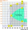
The fuel sharing system allows the engine to run on gas and liquid fuel in varying proportions, in order to optimise plant operation for a given availability of fuels. For example, if the gas available allows only 30% of the rated output to be reached, the engine will use fuel oil to achieve the remaining 70%. The operator can change the setpoint of the fuel share at will, while the control system ensures that the actual operating point is within the specified operating windows. The operator also has the choice of running the engine in conventional GD or fuel oil operation. The range of operation is shown in Figure 1.
Considering each part of the fuel sharing window individually:
Fuel oil operation. Fuel oil operation is based on the use of standard fuel oil injection pumps and the system operates just like a diesel engine. The engine can run for example on LFO, HFO or crude oil as the main fuel (and as the pilot injection fuel), without any changes to the fuel injection system. Fuel oil operation is available within the full range from zero to the rated load of the engine.
GD operation. GD is the original gas-diesel operation, where gas is the main source of power although pilot fuel oil injection of around 5% is used to ignite the combustion. GD operation is available between 30 and100% of rated load, and the transfer to or from GD operation can be executed at any point within 30 and 87.5% of rated load.
Fuel sharing operation. The fuel sharing option is available between 35 and 100% of rated load. The fuel share setpoint can be adjusted on-line from WOIS (Wärtsilä Operators Interface System). For example the operator may want to run at 30% gas share at full engine load, and to achieve this the 30% setpoint is entered and the fuel sharing mode selected.
If at any time the engine load is too low to reach the selected setpoint, the control system automatically adjusts the setpoint according to the minimum or maximum limit. If the load returns to a level where the 30% setpoint can be reached, the system will bring the fuel share back to the setpoint. The operator may change the setpoint at any time during operation.
Fuel sharing is limited to a specified window to ensure safe operation. The following numbers refer to the limiting points indicated in Figure 1:
1. The minimum gas proportion is equivalent to 15% of power generation at full load. This is a fixed limit that derives from the minimum gas injection volume: when the load is decreased, the lower limit becomes proportionally higher (ie a higher percentage value). The minimum gas share is defined in order to allow continuous operation only at sufficiently long injection durations to ensure repeatable and linear operation of the gas injection valve.
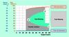
2. The maximum gas share in fuel sharing mode is about 80%, at 87.5% of the engine's rated load. The reason for not allowing continuous operation between GD operation and the maximum limit is that the fuel oil pump curve contains an inverse operating area between the main and pilot injection curves; inverse operation means that increasing the fuel rack position actually decreases the fuel injection amount. This area is bypassed in a step change when transferring to GD operation. The transfer area is illustrated in Figure 2.
3. Minimum engine output in fuel sharing mode is 35% of rated load, and this is the point where the minimum and the maximum fuel share limits meet. If the engine load goes below 35%, the system will automatically switch over to fuel oil operation. The switchover is executed as a fast transfer (not as a gas trip), which means that the gas supply system is maintained in ready status for some time to enable rapid return to fuel sharing should the load level quickly be restored above 35%.
The actual fuel sharing value is derived from the actuator positions. To reach an accurate actual value, the control system works internally with linearised actuator signals calibrated to site conditions and site fuels. The accuracy is best if the fuel heat value does not vary. However, the system is tolerant of variations and they do not cause problems in operation.
The technology
The fuel sharing system is essentially a combination of the GD engine and a new control system and control principle. The system controls both the gas and the oil injection simultaneously and allows both to be used within the allowed operating window limits. The new control system is tightly integrated into the programmable logic control (PLC) of the Wärtsilä extended level automation system using the Quantum platform.
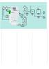
The fuel sharing system consists of multiple control loops which are all run under one central processing unit (CPU). The gas and speed control configuration is shown in Figure 3.
The speed and load are controlled by a dedicated PID controller embedded in the main PLC software. The speed controller provides a wide variety of optimised control methods such as speed droop, kW and speed droop compensation controls (SDC).
The fuel oil and fuel gas proportions are controlled by a dedicated twin-driver actuator controller which is also embedded in the PLC software. It receives the global control level signal from the speed PID, and divides the signal for the two actuators according to the set points and operating conditions.
The PLC control signals are connected to the actuators, which translate the global control signals into fuel injection cycles for each cylinder with the correct timing and duration. The fuel oil actuator is electro-hydraulic, the same as in conventional diesel engines. The gas actuator is an electronic rail valve (ERV) system which controls cylinder-specific injection valves based on engine speed and position, and a global control signal from the PLC.
In addition to the twin-driver function, the embedded controls include the gas supply pressure control, which keeps the gas pressure within the range 250 to 350 bar depending on the gas injection level. With small gas injection amounts (low fuel share or low output GD), the gas pressure is kept lower to extend the duration of the injection phase.
The high-pressure (HP) sealing oil pressure control is tightly integrated to the gas pressure control. The sealing oil pressure is kept 20 bar higher than the gas pressure, which means that the HP oil pressure tracks the gas pressure at all times.
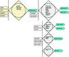
Last but not least, the system integrates the sequencing of the gas supply valves and the safety functionality. Without going into too much detail about the sequencing, the gas supply valves have the following functions:
• The double gas supply main valves secure the isolation of the gas source from the
engine, should this be necessary.
• A slow filling system is used during starting up. The gas line is filled through a smaller bypass line to prevent sudden pressure
variations in the system.
• The blowdown system is used for
recirculating the compressed gas back to the gas compressor inlet when the gas is shut off from the engine.
• The double venting valves are used for flaring the residual gas from the gas piping after blow down.
• The gas safety system will execute a gas trip and shut off the gas supply to the engine.
The main embedded control functions are shown in Figure 4.
Applications
The fuel sharing principle was originally tested on a Wärtsilä 4R32GD, in 1999, for LNG tanker applications. The test was performed manually, and it showed that the system worked, but development was not taken any further at that time.
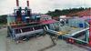
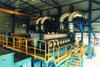
In 2002 Wärtsilä was contacted by Dygoil, an Ecuador-based company, with a specification which called for true fuel sharing capability for an oil field power supply system. Dygoil, with its partner Petroproducciòn Oil Government Co, needed a power plant that could run on both gas and crude oil because the gas supply was not stable and oil field gas availability declined over time as the watercut increased. Wärtsilä took up the challenge and developed the fuel sharing system for the 2x16V32LNGD project in a very short time. The plant was handed over for commercial operation in March 2004.
The Dygoil project best shows the main market niche for fuel sharing – associated gas in oil fields or refineries. However, the fuel sharing capability is not limited to this type of application. The fuel system can be used with gas that has a low methane number and with very low heat value gas (in fuel sharing, and partially in GD).
The fact that it combines a large variety of fuels may also make the fuel sharing system the most economical solution in certain cases. Since the control system is now integrated into the Wärtsilä standard extended level automation system, gas conversion applications or future gas conversions are now much more attractive than with the original GD system.
The main advantages of the fuel sharing system are:
• Flexible operation at variable gas/oil shares
• Flexibility in fuel oils, for example LFO, HFO and crude oil can be used as main and pilot fuel
• The system can operate on a low methane number gas
• The system can use low heat value gas,
especially in fuel sharing.
Does it work?
During the development of the fuel sharing system the development team was often asked whether such a system was really possible. Perhaps the idea of combining so many different and demanding fuel types into one system sounded too good to be true.
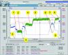
However, as the test runs in May 2003 and the commissioning runs in March 2004 showed, the system really works, and well too. The trends recorded in figures 5 and 6 show how the system transfers seamlessly from one operating point to another.
The fuel sharing system has now taken its place in the Wärtsilä power plant application portfolio as the solution for demanding fuel gas applications.
Key to Figures 5 and 6
- 0 35% load in fuel oil operation
- 1 35% load in fuel sharing operation, 40% gas share
- 2 35% load in gas diesel operation
- 3 Automatic transfer to fuel oil operation as load drops below 30%
- 4 60% load in gas diesel operation
- 5 80% load in gas diesel operation
- 6 80% load in fuel sharing operation, 20% gas share
- 7 80% load in fuel sharing operation, 75% gas share
- 8 Transfer to gas diesel operation, 80% load
- 9 Manually activated gas trip to fuel oil operation