Carbon capture & storage
Capture readiness: CCGT owners needn’t feel left out
1 December 2009It looks likely that gas fired combined cycle plants will need to be retrofitted with carbon capture systems in the future, and need to be demonstrating capture readiness now, certainly in the UK. What are the options for raising the steam that is likely to be needed to regenerate the solvent in a post combustion system?
When it comes to carbon capture and storage it may seem that coal is getting all the attention. But developers of natural gas combined cycle gas turbine (CCGT) plants really shouldn’t feel left out, certainly in the UK. New UK regulations for making power plants CO2 capture ready (CCR) apply to all CO2-emitting power plants at or above 300 MW output. And the UK Committee on Climate Change is looking for a rapidly falling level of emissions from the electricity sector. By 2030, any plant running for extended periods will probably have to be able to achieve annual average emissions levels of 100 kgCO2/MWh or less (vs 350 to 500 kgCO2/MWh for NGCC without CO2 capture).
As Figure 1 shows, between 2020 and 2030 electricity sector CO2 emissions will be expected to fall progressively. More and more existing power plants, including natural gas CCGT, will have to be retrofitted with CCS to do this. The eventual proportions of low-carbon electricity coming from renewables, nuclear and CCS respectively in 2020, 2030 and beyond are currently a matter of debate – and will actually be a matter of what can be financed and built in time. But the value for the UK and the plant owners in having an effective CCS option as a hedge against this uncertainty is clear.
What will CCGT capture look like?
There is, however, less clarity at present as to what CO2 capture retrofitted to a CCGT plant will look like in the 2020s. And perhaps capture won’t even be fitted to the CCGT plant itself. If hydrogen is supplied to modified CCGT plants instead of natural gas then the CO2 capture, transport and storage problem is shifted elsewhere, perhaps to a gasification plant fuelled by coal instead of natural gas. A separate hydrogen production site will almost certainly be well-situated for CO2 capture and transport to storage sites, but a possible hydrogen transport problem does have to be addressed instead.
But unless the power plant developer also makes plans specifically for a gasification plant on site (and the necessary coal or other solid fuel supply if gasification is proposed instead of natural gas reforming), then a ‘hydrogen from somewhere’ approach to retrofitting CCS cannot be relied on, and this is recognised in recent carbon capture readiness guidance from DECC in the UK (Dept of Energy and Climate Change, Carbon capture readiness (CCR): a guidance note for Section 36 Electricity Act 1989 consent applications, URN 09D/810, November 2009. http://www.decc.gov.uk/en/content/cms/consultations/ccr_consultati/ccr_consultati.aspx). ‘Pre-combustion’ capture from natural gas reforming to produce hydrogen is also possible, but the relative costs for this are likely to be quite high compared to post-combustion capture with natural gas as fuel, as shown in Figure 2a.
Instead, the costs presented in Figure 2 suggest that an option for post-combustion capture of CO2 from the flue gases leaving the heat recovery steam generator (HRSG) should be retained if at all possible. It should also be noted that the values reported in Figure 2 are based on conventional gas turbine operation. Recycling flue gas to replace a fraction of the air entering the gas turbine compressor might reduce post-combustion capture costs even further. Capture equipment capital costs would go down in this case because smaller gas volumes have to be processed in the capture unit (but similar gas volumes would be retained in the rest of the plant, upstream of the recycling point). CO2 concentrations would also increase, making high levels of capture easier. Against this must be set the capital cost of recycling ducts etc, which is likely to be increased if they have not been allowed for in the capture ready design.
But as Figure 2b shows, the additional capital cost penalty for post-combustion CO2 capture from natural gas-fired CCGT plants is expected to be a relatively small part of the total abatement cost penalty (about 30% of the total in this example). Roughly another 20% is additional operating expenses, mostly solvent consumption. The main additional cost for CO2 abatement (50%) is the extra fuel that has to be burnt per unit of electricity supplied to the grid, because of the reduced efficiency of the power plant when some of the energy in the fuel has to be used to operate the CO2 capture and compression equipment.
About half of the capture fuel/energy penalty for the post-combustion capture case shown in Figure 2 arises because of the heat required to regenerate the solvent, currently expected to be an amine or ammonia solution, used to ‘scrub’ the CO2 out of the flue gases. This heat is likely to be supplied by condensing steam, which can provide the heat at a single temperature and also poses no risk of damaging the solvent by overheating (as could occur if the solvent was directly heated in the HRSG – which would probably
also involve significant equipment modifications). In this example in Figure 2 the steam was assumed to be taken from the steam cycle just upstream of the low pressure (LP) cylinder and the pressure at the IP/LP crossover between the intermediate and low pressure cylinders was set at 3.6 bar, to give the required steam temperature in the solvent ‘reboiler’. In this particular example it was also assumed that the plant would not require the capability to operate without CO2 capture, so the steam turbine LP cylinder was undersized (for about 50% of the normal flow without capture).
Additional electrical power, the other half of the overall fuel/energy penalty, was required to compress the captured CO2 from about 2 bara up to 110 bara, into a dense phase for pipeline transport. Interestingly, some of the heat required for solvent regeneration can also
be regarded as providing CO2 thermal compression. The CO2 starts out at a partial pressure of around 0.04 bara in the flue gases and leaves the solvent stripper column already at 2 bara. The solvent used in this example was Fluor’s Econamine FGplusTM, based on monoethanolamine (MEA). The CO2 pressure in the stripper is limited by the peak temperature that can be used, which is in turn limited by the thermal stability of the solvent. But if more thermally-stable solvents are available (eg, ammonia solutions) then higher temperatures in the stripper, and consequently higher CO2 pressures at the compressor inlet can be obtained. Of course, if the steam has to be supplied at a higher pressure then it could have done more work in the LP turbine, but favourable trade-offs between reduced LP power output and reduced compressor input power are likely. This means that it is not possible to be sure what steam pressure will be required in the future to allow the most efficient capture process to be used.
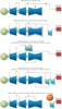
Ancillary boiler vs integrated retrofit
Perhaps because of the difficulty of specifying future steam pressures, and also because of the loss in electricity output, some commentators have suggested that future steam requirements when a plant is retrofitted should be met by adding a separate ancillary boiler, as in Figure 3e. But this is neither necessary nor recommended. Steam can be extracted efficiently using the existing steam turbine IP/LP crossover (Figure 3a-b). Additionally, if the pressure here is too low or a combined IP/LP cylinder is being used with no ready extraction points then it is also possible to consider extracting steam from the hot reheater (RH) exit or intermediate pressure (IP) cylinder inlet, as shown in Figure 3c-d and expanding it through one or more turbines added at the time of the retrofit.
The drawback with using a separate boiler (3e) is obvious. Power plant engineers have spent a great deal of time improving the efficiency of natural gas-fired CCGT plants up to the current 55-60% LHV level because it makes economic sense to do so. To achieve such high efficiencies the energy in the natural gas is first used at very high temperatures in the gas turbine, then steam is raised from the gas turbine exhaust. As a result, low grade heat is rejected in the gas turbine exhaust at around 100ºC and in the steam cycle condenser at around 30ºC or lower if possible. Schemes that integrate capture steam requirements with the steam cycle nearly repeat the above, differing just in the temperature of heat rejection in the steam cycle. Some of the steam is condensed in the reboiler at 100ºC to perhaps 150ºC (depending on the solvent used). In contrast, capture plants with separate boilers do not make use of the full potential of the fuel calorific value. They just turn the energy in the gas to heat at this same low reboiler temperature, missing out all of the opportunity to extract higher-grade electrical energy. If a back-pressure turbine is used upstream of the reboiler, it still extracts less electrical energy than would be feasible if, for example, the boiler was replaced by an additional combined cycle gas turbine.
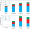
These shortcomings of boiler retrofits versus integrated retrofits are shown in the estimated retrofit performance results of Figure 4. The integrated retrofits (3a-d) all achieve efficiencies of around 46-47% LHV. Although the boiler retrofits (3e) do not see the same drop in power output from the plant, especially when the steam from the boiler is used to generate additional electricity in a back pressure turbine, their efficiencies are only 41-43% LHV. Since fairly similar levels of emissions (60-70 kgCO2/MWh – it is assumed that emissions from the boiler have to be captured) are achieved for all the options, the drop in efficiency means that approximately 50-80% more additional gas is consumed per tonne of CO2 abated with boiler retrofit cases. If the fuel constitutes a major part of the cost penalty for capturing CO2 (ie, unless natural gas prices are low) it is therefore apparent that boiler retrofits are likely to require a significantly higher carbon price to become viable. Some reduction in capital costs may be achievable by utilising CCGT flue gas in the boiler instead of air, but this would have to be set against the cost of additional ducting and a non-standard boiler design.
The need to examine the viability of a boiler retrofit is confirmed in the recently published UK DECC guidance on carbon capture readiness already mentioned, which states that:
“Standalone boilers are not considered as efficient a method of providing steam for regeneration of the chemicals as an integrated capture system in which steam is extracted from within the CCGT or coal power station itself. If applicants choose a standalone boiler as part of their proposals for the retrofit of carbon capture equipment, they must justify this choice and demonstrate that it could be considered comparable to an integrated system once carbon capture is operational … this could be by providing evidence that the standalone system... was as thermally efficient per unit of CO2 as an integrated system once carbon capture is operational for their particular power station.”
It is also interesting to consider how valuable maintaining the same continuous output by adding a boiler would be in future low-carbon electricity markets. A common feature of low-carbon markets is likely to be a much higher fraction of generation from intermittent renewables, mostly wind, than now. Under these circumstances fossil plants with capture are likely to be operating at part load for extended periods, providing back-up services as well as electrical energy. The ability to recover the ‘lost’ output from the plant by interrupting capture or using stored solvent (this requires retrofits 3a, 3c-3d rather than 3b, unless an additional LP cylinder that can be connected by a clutch is provided) may also offer additional, and possibly more effective, ways to provide grid services than just operating the CCGT and capture plant at varying part load.
Close integration needed
Of course, combined cycle plants with the capacity for integration with post-combustion capture will differ from previous ‘standard’ designs, for which CO2 capture was not a consideration. But with growing expectations that low-carbon electricity is the key to a low-carbon society it seems likely that the slight modifications required to allow subsequent cost-effective operation in capture mode, with close integration with the capture plant, will emerge as a new standard before too long!