GAS TURBINE COMBUSToR OPTIMISATION germany supplement
Cleaning up in the heart of Berlin
1 December 2006A combustion optimisation package installed at Vattenfall Europe's Berlin CHP plant has lowered NOx emissions significantly and reduced trips.
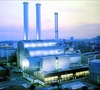
In the centre of Berlin, Vattenfall Europe operates a combined heat and power plant consisting of two Alstom GT13E2 gas turbines with exhaust heat recovery boilers and a steam turbine (Figure 1). The use of exhaust energy for district heating leads to a total thermal efficiency of 89% (51% electrical efficiency). The two GT13E2’s were commissioned in 1996 and as of mid June 2006 had accumulated more than 40000 operating hours.
When introduced in 1993, the GT13E2 was the first commercial heavy duty gas turbine to be equipped with a dry low NOx annular combustor. The combustion chamber is cooled by a combination of convective and film cooling. The combustor incorporates 72 so called EV burners (EnVironmental burners), which are the standard low NOx units in all Alstom gas turbines.
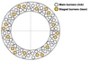
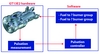
Since dry low NOx combustion systems are operated in lean premixed mode, they have only a narrow low NOx operation range. In order to provide stable combustion at part load, burner staging is applied to the GT13E2 during premix operation down to 60% relative load. Burner staging is achieved in the GT13E2 by splitting the premix gas fuel system into two groups (Figure 2):
1. A rich main burner group, which is operated in a fuel rich and stable mode. This group includes 3/4 of the total number of burners (54 burners).
2. A lean staged burner group, which can be operated below the flame stability limit and is used to control the gas turbine load at part load. This group includes the remaining 1/4 of burners (18 burners).
Optimisation package
Alstom offers several power and lifetime upgrades of the GT13E2 and in 2005 the company’s combustion optimisation package was introduced in one of the Vattenfall units. The upgraded machine has been in operation ever since.
The combustion optimisation package implemented at the Berlin plant focuses on three major issues:
• flame stability;
• homogenisation of flame temperature distribution in the combustor; and
• combustion control logic.
Using numerical simulation of the reacting flow in the combustion chamber (Figure 3) modelling was carried to analyse improvements to the cooling air distribution, by adding thermal barrier coating (TBC) to the primary flame zone combustor walls (Figure 4) and optimising film cooling in the downstream section. The results of the simulation indicated a clear improvement in flame shape though the downstream temperature distribution hardly changed. This is important, since it is necessary that changes to the combustor do not influence the turbine inlet conditions.
To make full use of the low NOx capabilities of the EV burner, the flames of the individual burners have to be operated in a narrow flame temperature window. However the flame temperatures of the individual burners can scatter significantly due to distortions in the airflow, the fuel flow and due to manufacturing tolerances of the combustor hardware. The most efficient way to reduce the scatter in flame temperatures is to adjust the fuel flow to the individual burners. For this purpose, the temperature of each individual burner has to be determined.
Since the mixing of combustion gases in the GT13E2 combustor is very intense, temperature measurements downstream of the combustor (eg after the turbine) do not allow the flame temperature distribution to be derived. Therefore, an optical method was chosen to directly measure the flame temperature of each burner, a method which Alstom calls “flame sensing.” Flame sensing uses the chemo luminescence radiation of the OH radicals emitted during the reaction of hydrocarbons with oxygen to determine the flame temperature. For this purpose, the 72 EV burners are equipped with optical fibre sensors to measure the radiation of the flames, while the fuel line of each burner contains a valve to adjust the fuel flow.
Completing the combustion optimisation package is a closed loop combustion control system, which Alstom calls APCL (advanced pulsation control logic). APCL (see Figure 5) makes direct use of the pressure pulsation signal measured in the combustor and adjusts the fuel distribution between the two burner groups (main, 3/4, group and staged, 1/4, group) in such a way that the flame stability is ensured under all circumstances.
The complete combustion optimisation package was installed in the Vattenfall Europe Berlin plant in July 2005.
Reduced emissions and shutdowns
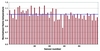
The individual burner flame temperatures were determined using the flame sensing technique described above. Figure 6 shows the status of the flame temperature distribution before homogenisation. The values are normalised with the average flame temperature of the measured main group burners to simplify the identification of hot burners. Hot-fired burners, with flame temperature up to 14% over the average, can be identified from the figure. This kind of pattern is to be expected for a ten year old plant.
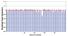
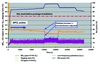
The hot burners were throttled using their individual tuning valves until the maximum deviation from the average flame temperature was reduced to <5%. This was checked by a final flame temperature scan of the complete combustor (Figure 7). One burner (number 39) continued to show a low flame temperature. The reason for this might be an obstruction in the gas injector (eg due to dirt or deposits). But as it was only one burner this was acceptable. The burner will be checked during the next inspection and replaced if necessary. The advanced pulsation control logic was installed in the gas turbine control software without problems. After adjustment of the control parameters, the unit was handed back to Vattenfall for commercial operation. Figure 8 shows a record of operating parameters and emissions for normal start up and operation of the gas turbine. After synchronisation, the gas turbine is operated for a short time with a pilot diffusion flame. Above 60% relative load the APCL is active and reduces the NOX emissions to below 20ppm. For the complete operating period the NOX emissions stay within a range of 15 to 20ppm.
Most of the time APCL operates within the normal pulsation settings. The function of APCL is best seen during the steep load gradients at 15000s and 20000s. The load change leads to a sudden pulsation peak, to which APCL reacts by reducing the staging ratio (the ratio of fuel which is supplied to the staged, 1/4, group) and thus enriching the main burner group. Subsequently APCL adjusted the fuel distribution again according to the given pulsation characteristic. This shows the capability of APCL to dynamically respond to distortions in the combustion process, allowing the gas turbine to be safely operated closer to the lean extinction limit than with a given static control matrix. Figure 8 further demonstrates the significant reduction in NOx emissions compared with the level before installation of the package.
Reductions appreciated
The emission reductions achieved are greatly appreciated by the power plant management. In addition, following installation of the combustion package, the number of unexpected engine shut downs (trips) has reduced by 60%, compared with before the installation. This reflects the beneficial effect of the package on flame stability. The improved reliability is commercially of great value for Vattenfall in the competitive power production environment in Germany. Following successful validation in Berlin Alstom has now installed the combustion optimisation package, or parts of it, in many GT13E2 power plants within Europe.
Figure 1. A view of the Vattenfall Europe Berlin combined heat and power plant Figure 2. Arrangement of the main (3/4 group) and staged (1/4 group) burners in the GT13E2 combustor Figure 3. Temperature distribution from numerical simulation of the reacting flow field in the GT13E2 combustion chamber Figure 4. TBC coated combustor wall in the primary zone, on the right the EV burner outlet is visible Figure 5. Principle of the APCL system Flame temperatures (normalised by the average flame temperature), before flame homogenisation Flame temperatures (normalised by the average flame temperature), after flame homogenisation Figure 8. Example of APCL function during GT operation