HEAT?RECOVERY?STEAM?GENERATORS
Dealing with cycling: TRD 301 and the Euro Norm compared
1 October 2007What does European Norm 12952-3 mean for the assessment of HRSG cycling fatigue analysis and assessing cumulative damage due to cycling? CMI has done an in-depth comparison of EN?12952-3 and TRD 301.?
With combined cycle units now being increasingly required to supply power to the grid as and when needed, at short notice, consideration of cycling has become an integral feature of HRSG design. But the ASME Code assumes continuous operation at design conditions, and does not cover cyclic assessment or mandate fatigue analysis. Up until fairly recently European boiler makers used the German code, TRD 301, for such analysis. However, European Norm 12952-3 has now superseded TRD 301 for cycling fatigue analysis and for calculating acceptable pressure/time gradients. Therefore in Europe HRSGs are designed according to ASME but then subjected to fatigue analysis in accordance with European Norm 12952-3, which derives largely from TRD 301 but which has a few significant differences.
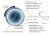
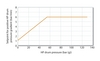
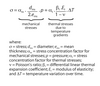
Figure 1 shows a curve from European Norm 12952-3 relating allowable number of start up cycles, fatigue and tensile strength. The Euro Norm suggests that a cold start is up to 20 times more damaging than a warm start, and that the stress range resulting from a hot start is typically below the fatigue limit and does not contribute to total fatigue damage (except in regard to quenching, see later). Fatigue damage is very sensitive to stress range (note double logarithmic scale of Figure 1).
In practice, the input data for the Euro Norm are component diameter, material, thickness and operating pressures and temperatures. From this the number of cycles can be calculated for given start-up and shutdown rates, or the allowable rates can be calculated for a given number of cycles.
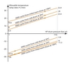
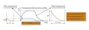
For both codes as pressure increases, the allowable pressure ramp rate also increases (see Figure 2). In practice, Euro Norm fatigue analysis is applied to the thick HP drum wall as well as to the outlet headers of the reheater and HP superheater.
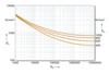
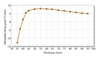
A cold start is the most stressful event in terms of fatigue effect, as it encompasses the largest cycle range. Unless required otherwise by a specification, the number of cold start-ups considered by CMI is 2000 over a 20 year design lifetime. Applying the Euro Norm in the case of a large number of cold starts produces negative temperature gradients (Figure 3). This is of course not possible, and means that the material has no strength left to accommodate such a large number of start-ups, ie, that cumulative cycling has consumed the component fatigue lifetime.
Overall, both TRD 301 and the Euro Norm require a drum to be operated in the stress range of minus 600 N/mm2 (to protect the internal magnetite layer) and plus 200 N/mm2 (see panel, p37).


Improvements in Euro Norm 12952
TRD 301 was generally seen as the reference for pressure vessel cycling analysis. However, when compared with finite element (FE) analysis, this code turned out to be somewhat conservative. For instance, TRD assumed empirically derived stress concentration factors around nozzles. These were found to be high when compared with finite element results, reflecting the fact that measures are taken in HRSG construction to avoid sharp edges in these locations. Also, the feedwater nozzle on drums is always equipped with an internal thermal sleeve to accommodate the induced thermal shock without undue stresses when cold feedwater first flows into a warm drum.
Indeed it is in the determination of these stress concentration factors where Euro Norm 12952 represents the biggest improvement over TRD 301, precisely because it allows the use of finite element methods.
To fully capture all the differences between EN 12952-3 and TRD 301, a survey of the two codes was conducted by CMI on a specific boiler. The TRD 301 and EN 12952-3 calculation methods are similar, but some differences were identified, mostly related to the empirical coefficients used in the formula for stress evaluation:
A summary of differences between the two codes is shown in Table 1.
The critical components are the HP drum and high temperature superheater/reheater headers and/or manifolds. Table 2 shows results obtained from analysis of the connection between the branch (nozzle) and main body of an HP drum and an HP superheater.
Comparative cumulative damage figures are shown in Table 3.
The comparison confirms that the most important improvement in the Euro Norm over TRD 301 is in the area of stress induced factors. Euro Norm appears to be less conservative than TRD 301, and better reflects the physics.
One thing not considered in the Euro Norm is superheater quenching, which occurs due to the presence of condensate water inside the still-hot superheater during initial gas purging. This quickly cools some parts of the component relative to others, and induces low cycling fatigue cycle in the overall warm start-up cycle. Although the phenomenon is damaging, it is very difficult to take account of because of its empirical nature. As it is absent from Euro Norm, good engineering practice must prevail in the form of an effective drainage system.


Optimising drum design
Four materials are typically used for HRSG drums, SA 302 Gr B, SA 299, SA 516 Gr 60, and SA 516 Gr 70.
There is a trade off between SA 302 Gr B and SA 299, such that, at about 100 bar, a drum made out of SA 299 becomes far too thick compared with a drum made out of SA 302 Gr B.
The latter material is generally used for HP drums to reduce wall thickness, which has a big effect on thermal stress. The two other materials are mainly used for lower pressure drums, where fatigue is not an issue (low pressure, low thickness).
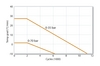
Performing the Euro Norm calculation with the same inputs, but with the drum thickness as a free parameter, it is interesting to note there is an optimum in the allowable temperature gradient (Figure 4), which can be explained as follows. As a result of the temperature gradient across the drum thickness, thermal stress on the inner shell increases roughly as the square of the wall thickness, while mechanical stress decreases in proportion to the thickness (see panel, p 37). Therefore, during cold start-up, the inner thermal stress quickly becomes predominant, and consequently reduces the allowable temperature gradient.
Coincidentally, the calculated wall thickness according to the ASME code is typically close to the optimum wall thickness calculated according to the Euro Norm in terms of material fatigue considerations.
Considering a two downcomer drum, and comparing it with an equivalent three or four downcomer drum (ie with comparable circulation rates), calculations show that the drum equipped with thicker downcomers has a better fatigue resistance. The results are summarised in Table 4.
However, this result does not generalise to other components. Indeed, when performing the same kind of calculation for header and tube connections, the opposite could be concluded.


Drum/superheater nozzle weld configuration
Three attachment designs are typically used in the boiler industry. The Euro Norm specifies Stress Induced Factors (SIF) for each of these as shown in Figure 5.
In the CMI standard design the following attachment configurations are used:
• on drums: set-through nozzle (with/without internal extension) (implemented for several years);
• on superheater headers: set-on nozzles/ branches without root weld reappropriation whenever fatigue analysis allows it, and ground over (ie with stubs) when required by fatigue analysis.
Note that calculations for attachment connections using reinforcing pads cannot be done directly using Euro Norm formulae, a finite element analysis is required.
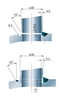
For HP superheaters and reheaters of alloyed steel and subject to water quenching, the CMI standard tube to header welding attachment is always set-on with full strength penetration welding (Figure 6a). This design goes beyond ASME minimum requirements. But, for economiser and evaporator, partial penetration welds (Figure 6b), specified by ASME, are proven under cycling conditions.
Optimisation of boiler start-up time
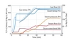
As noted earlier, the allowable temperature gradient increases as pressure builds. These calculated temperature/time gradients are converted into pressure/time gradients, which are more accessible and controllable parameters during transients. These are used to optimise start-ups by applying progressive pressure ramp rates (Figure 7), which allows optimisation of the overall boiler start-up time, without consuming any extra boiler lifetime. Such progressive pressure gradients are always implemented in the plant DCS by CMI, either via a curve of variable controlled set points on the HP steam turbine bypass valve (Figure 8), or via various HP pressure control set points during start-up. Until the condenser is ready, the boiler relies on superheater start-up vents sized ad hoc. Only the HP drum pressure needs to be controlled, and no limitations are imposed on the IP and LP circuits because those are less critical items for fatigue. However, the bottleneck in the overall cold start-up time is typically on the steam turbine side, rather than on the boiler side.
Main findings
CMI's main findings can be summarised as follows:
• Compared with TRD 301, Euro Norm 12952-3 represents an improvement in methodology, but it is still conservative. To better approach reality, stress concentration factors can be determined by finite element analysis and used with the Euro Norm, which the code allows.
• Nozzle (branch) to main component attachments must be engineered to minimise fatigue. This means that set-through arrangements are better for drums, whereas set-on attachments are preferred for tube to header attachment.
• The Euro Norm allowable pressure gradients vary with pressure. Boiler start-up time can thus be optimised without consuming fatigue lifetime by using progressive pressure gradients. This interesting feature, derived directly from fatigue analysis, is used routinely by CMI.
• If possible, stress values should be obtained from finite element or finite difference calculations, to arrive at more realistic results.
• The sensitivity of the allowable number of starts due to the logarithmic and probabilistic nature of fatigue results in an inherent uncertainty in fatigue lifetime analysis. And
• Superheater water quenching, which remains the big cycling issue for hot start-ups, especially for horizontal HRSGs, is not taken into account in the Euro Norm. Following good engineering practice, provision of efficient HP superheater and reheater drainage is the key design measure to address this quenching problem.
We thank Pascal Fontaine (pascal.fontaine@cmigroupe.com) of CMI for his valuable input to this article.
HRSGs under stress – the basics
There are basically two kinds of stress inside the walls of HRSG components: mechanical stress arising from internal pressure; and thermal stress stemming from thermal expansion. During start-up, these stresses are in opposite directions, while during a shutdown they are in the same direction on the inner surface.
A cold start is more onerous than a hot start because the inner shell is heated up while the interior is at atmospheric pressure. That induces compressive thermal stress before it can be counter-balanced by tensile stress from pressurisation. As soon as pressure starts to increase, mechanical tensile stress releases thermal stress as they are in opposite directions. Therefore, the largest amplitude for this stress cycle happens during a cold start-up, the most severe condition experienced. In addition, the internal protective magnetite layer can crack during the early stages of start-up. This Fe3O4 is created naturally under pressure at normal drum operating conditions, and this dictates the lower stress limit, which is determined empirically.
During the subsequent pressure increase, the drum shell is heated from the inside by boiling water and the heat is transmitted from inside to outside generating a temperature profile. A significant temperature difference between the inner and outer shell surfaces builds up. The outer shell surface temperature lags behind the inner one. This shifting temperature profile has roughly a quadratic shape versus wall thickness, and so has the induced thermal stress profile. Once pressure is stabilised at the normal operating condition, this temperature profile will vanish, so will thermal stress, and only this mechanical stress will remain in the equipment wall. During shutdown, the same thing happens but in the opposite direction, with reversed temperature profile between external and internal surfaces on drum shells. This complete cycling stress, including start-up and shutdown, must be considered in component fatigue analysis.
The temperature difference between the inner and outer walls is roughly proportional to the square of the drum thickness, and so is the thermal stress. This is why thin walls are so beneficial in terms of cycling fatigue. For instance, it is generally considered that the thickness of a superheater outlet header made of P91 material can be reduced by a factor of 2 compared with the same header made in P22 material. Consequently, the induced thermal stress would be reduced by a factor of 4 for such a P91 header compared with a P22 header.