Power from waste
Positive verdict in RDF’s CFB trial
1 July 2007TEV Neumunster is a successful implementation of AE&E´S Powerfluid CFB design for incineration of RDF

Driven by new regulations for landfill, the municipality of Neumünster in Germany decided in 2003 to install a treatment plant for municipal waste that would include the thermal treatment of high calorific value refuse derived fuel with an LHV from 10 to 20 MJ/kg.
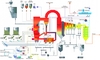
A circulating fluidised bed (CFB) boiler constitutes the core of the thermal treatment plant. Austrian Energy´s Powerfluid CFB technology was selected for this key component because of its good emissions performance in terms of flue gas criteria and dust emissions, and its fuel flexibility. Table 2 lists the basic design criteria for the CFB boiler. The flow diagram, Figure 1, shows the working principles of the Powerfluid technology for incineration of RDF.
Primary loop and FB heat exchanger
The cylindrical combustion chamber as well as the cyclone, the loop seal and the return leg are completely refractory lined and represent an adiabatic system. There are no heating surfaces inside the combustion chamber, a design feature that avoids corrosion effects and ensures excellent combustion conditions (sufficient residence time at temperatures > 850°C) for the entire load and fuel range. The combustion temperature is primarily controlled by heat extraction to an external fluidised bed heat exchanger, where the sensible heat of a portion of the circulating bed material is transferred to banks of superheater and evaporator tubes installed in the bed. Depending on combustion temperatures and load conditions the circulating bed material flow passing over this heat exchanger is adjusted and controlled by a water cooled needle valve.
Fine tuning of combustion chamber temperatures is realised by the use of recirculation gas. Approximately 35% of the combustion air is introduced into the combustion chamber as primary air via an open nozzle grid, while the rest is introduced via two secondary air level nozzles. With this kind of staged combustion and with operating temperatures lower than 800°C in the lower part and less than 900°C in the upper part of the combustion chamber very low NOx emissions levels can be achieved. The installed SNCR system is operated at minimum flow in stand-by mode most of the time.
RDF as the main fuel is directly fed onto the dense bed of the lower part of the combustion chamber by a pneumatic injection system consisting of three feed lines with separate blowers for each line, supplying sufficient pressure to overcome the back pressure of the bed. A velocity of more than 25 m/s in the feed lines ensures excellent fuel penetration into the dense bed and eliminates the risk of back burning. A stable, metered fuel flow, a thorough intermixing of fuel and bed material as well as a maximised flue gas residence time at a temperature > 850°C in the combustion chamber, the cyclone and the post-combustion chamber downstream of the hot cyclone are the pre-conditions for the unique burn out rates of AE&E´s Powerfluid technology. Bed ash is discharged at the bottom of the combustion chamber. An open type of nozzle grid (Figure 2) guarantees the separation of coarse material like wire, metal swarf and stones, which constituted more than 6% of total fuel input in 2006.

Radiation passes
Leaving the post-combustion chamber, the flue gas enters two membrane-walled radiation passes, the second of them also equipped with evaporator wing walls. The design of the heating surface coupled with a state of the art cleaning system ensure exit temperatures downstream of the second pass significantly below 650°C. This limit is based on experiences from waste incineration plants and has been regarded as important in managing the fouling effects on the heating surfaces of the following tube bundle. The superheating surfaces and the evaporator bundle of the tail-end pass are arranged as hanging tube banks. To minimise the risk of high temperature chlorine corrosion, all superheaters are arranged in parallel flow and the steam temperatures are kept below 380°C. The cleaning system for these heating surfaces consists of a mechanical rapping device and retractable sootblowers. The final superheating is performed in the external fluidised bed material heat exchanger described above.
Multicyclone and economiser
A pre-dust-collector consisting of 4 cyclones (in parallel flow) is installed between the tail-end pass and the economiser. This multicyclone facilitates the removal of approximately 70% of the fly ash from the flue gas flow at temperatures of above 400°C. At lower temperatures there can be re-contamination by the formation of dioxins and furanes by the mechanism of de novo-synthesis.
To allow the injection of activated carbon at the following baghouse filter, the temperature of the flue gas leaving the ECO is limited to 160 – 170°C. This is achieved by adjustment of the feed water temperature, where the a minimum temperature of 130°C is brought about by a low pressure steam preheater; fine tuning up to the required level is done by a drum pre-heater. A steel shot cleaning plant removes fouling layers from the tubes.
Operating experience
The first operational data are very promising. Table 1 shows that all performance guarantees could be proved during the performance test carried out in September 2005. Table 2 includes the operating time of the CFB boiler and the RDF (“Ersatzbrennstoff”) throughput since the start of operation.
Although the ash content of RDF and especially the impurities carried along with the fuel (such as metal fragments, stones, and ceramics) are significantly higher than was originally expected, it has not been necessary so far to go into boiler shutdown owing to agglomerations of coarse particles in the bed. All impurities can be safely discharged via the open nozzle grid.
The emission figures in Table 4 demonstrate that all expectations concerning burn out rates and low NOx emissions with this unusual CFB design have been met or even exceeded.