Genset developments - noise reduction
Sound advice
1 February 2008With the growth of standby, prime and peaking power installations in highly populated areas, design engineers have focused their attention on understanding how generator set noise is propagated and controlled. The high cost of retrofitting a site for noise reduction makes it imperative to assess noise performance requirements early in the on-site power system design stage. By applying the principles outlined here, power system designers and end-users alike will be able to more easily control unwanted noise from their on-site power system.

Like many types of rotating machinery, reciprocating-engine-powered generator sets produce noise and vibration. Whether these generator sets run continuously in prime power applications or only occasionally in standby applications, their operating sound levels often must be reduced to comply with local, state or federal ordinances. In North America, maximum permitted overall noise levels range from 45 dB(A) to 72 dB(A), depending on location and zoning. In fact, recently, some states and communities have begun to specify property line noise restrictions using octave band frequencies to reduce the amount of low-frequency noise that reaches community neighbourhoods. Since untreated generator set noise levels can approach 100 dB(A) or more, both the location of the generator set and noise mitigation take on great importance.
In general, two forms of regulations affect the volume of noise to which individuals or the public may be exposed: state or municipal noise ordinances; and Occupational Safety and Health Administration (OSHA) federal safety regulations. The former regulations address noise that may migrate beyond property lines and disturb the public but that is seldom sufficiently loud to constitute a safety hazard. The latter addresses standards for noise exposure in the workplace to protect the health of workers. OSHA regulations normally only apply to workers who may be exposed to generator set noise that is above 80 dB(A) for any appreciable time. Workers can limit exposure by wearing proper hearing protection when working around operating generator sets. Europe and Japan, as well as numerous other countries, have also set standards to control noise in the workplace and in the environment at large.


What noise annoys?
Sound is what the human ear hears; noise is simply unwanted sound. Sound is a variation in pressure in the region adjacent to the ear. When the amount of sound becomes uncomfortable or annoying, it means that the variations in air pressure near the ear have reached too high an amplitude.
The human ear has such a wide dynamic range that the decibel (dB) scale was devised to express sound levels. The dB scale is logarithmic because the ratio between the softest sound the ear can detect and the loudest sound it can experience without damage is roughly a million to one. By using a base-10 logarithmic scale, the whole range of human hearing can be described by a more convenient number that ranges from 0 dB (threshold of normal hearing) to 140 dB (the threshold of pain).
There are two dB scales: A and L.
• The dB(L) unit is a linear scale that treats all audible frequencies as having equal value. However, the human ear does not experience all sound frequencies as equally loud. The ear is particularly sensitive to frequencies in the range 1000 to 4000 Hz, and not as sensitive to sounds in the lower or higher frequencies.
• Therefore, the "A-weighting filter," which is an approximation of loudness, is used to correct the sound pressure levels to more accurately reflect what the human ear perceives. This frequency-weighting results in the dB(A) scale, which was adopted by OSHA in 1972 as the official regulated sound level descriptor.
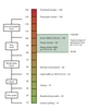
Figure 1 shows typical noise levels associated with various surroundings and noise sources.
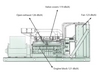
Generator set noise (see Figure 2) is produced by the following sources :
• Engine noise – This is mainly caused by mechanical and combustion forces and typically ranges from 100 dB(A) to 121 dB(A), measured at one metre, depending on the size of the engine.
• Cooling fan noise – This results from the sound of air being moved at high speed across the engine and through the radiator. Its level ranges from 100 dB(A) to 105 (A) dB at one metre.
• Alternator noise – This is caused by cooling air and brush friction and ranges from approximately 80 dB(A) to 90 dB(A) at one metre.
• Induction noise – This is caused by fluctuations in current in the alternator windings that give rise to mechanical noise that ranges from 80 dB(A) to 90 dB(A) at one metre.
• Engine exhaust – Without an exhaust silencer, this ranges from 120 dB(A) to 130 dB(A) or more and is usually reduced by a minimum of 15 dB(A) with a standard silencer.
• Structural/mechanical noise – This is caused by mechanical vibration of various structural parts and components that is radiated as sound.
Making measurements
Before you can begin to determine what mitigation might be required, you have to collect accurate sound measurements of both the existing ambient noise and the noise contributed by the generator set. Accurate and meaningful generator set sound-level data should be measured in a "free field environment." A free field, as distinguished from a "reverberant field," is a sound field in which there are negligible effects from sound being reflected from obstacles or boundaries.
Noise measurements should be made using a sound level meter and an octave band filter set, at a minimum, to allow for more detailed analysis by acoustical consultants.
When measuring sound levels from a distance of 7 metres,* microphones are placed in a circular array with measurement locations at 45-degree increments around the generator set. The measurement array is 7 metres from an imaginary parallelepiped that just encloses the generator set, which is usually defined by the footprint dimensions of the skid base or chassis.
When measuring sound power levels for European applications, a parallelepiped microphone array is typically used, as defined in ISO 3744.
Sound performance data for generator sets from Cummins Power Generation are available on the company's "Power Suite" design software CD. Sound performance data are also available in the Power Suite Library on www.cumminspower.com.
Initial noise measurements are usually made in eight octave bands, from 63 Hz to 8000 Hz, although the highest sound power generated is typically in the range 1000 Hz to 4000 Hz – the range of sound to which the human ear is most sensitive.
While measurements are taken across a spectrum of frequencies, the logarithmic sum of all the frequencies is the most important reading. However, when the overall sound level exceeds the allowable level for a project, frequency band data is used to determine what design changes are necessary to lower the overall sound level to comply with requirements.
The total noise level from a generator set is the sum of all the individual sources, regardless of frequency. However, because the dB(A) scale is logarithmic, the individual dB(A) readings cannot be added or subtracted in the usual arithmetic way. For example, if one noise source produces 90 dB(A) and a second noise source also produces 90 dB(A), the total amount of noise produced is 93 dB(A) - not 180 dB(A). An increase of 3 dB(A) represents a doubling of the sound power; yet, this increase is barely perceptible to the human ear.
Table 1 illustrates how to add decibels based on the numerical difference between two noise levels. As in the example above, if there is no difference between noise source 1 and noise source 2, their combined dB(A) measurement would only increase by 3 dB(A) – from 90 dB(A) to 93 dB(A). If source 1 was 100 dB(A) and source 2 was 95 dB(A), their combined dB(A) measurement would be 101 dB(A).
The regulations
In North America, state and local codes establish maximum noise levels that are permitted at the property line. Table 2 shows some representative outdoor noise level regulations. Compliance with these noise regulations requires an understanding of the existing ambient noise level at the property line without the generator set running and what the resultant noise level will ultimately be with the generator set running at full load.
In Europe, regulation of generator noise is governed by the 2000/14/EC (Stage II) legislation that has been in place since 2006. For generators with a prime power rating less than 400 kW, the maximum sound power level permitted is calculated using the formula:
95 + log Pel = dB(A)
(where Pel is the generator's prime power rating in kW).
Generators of 400 kW prime rating and above are only required to be labelled with the LWA figure (European measurement of "acoustic power level") calculated from the manufacturer's developmental test results. For the European market, most generators from 11 kVA to 550 kVA are packaged in standard enclosures that make the units compliant with most legislation. Standard enclosures typically reduce radiated noise by a minimum of 10 dB(A).
Strategies for reducing noise
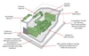
Typical noise control measures are shown in Figure 3. Regardless of the type of generator set, the basic strategies for reducing noise include the following (in addition of course to making the engine itself quieter, eg, by reducing combustor and injector noise): acoustic barriers; acoustic insulation; isolation mounts; cooling air attenuation; exhaust silencers; and maximising the distance between the generator set and the property line (or people).
• Acoustic barriers: rigid materials with significant mass and stiffness reduce the transmission of sound. Examples include sheet steel typical of enclosures, and concrete- or sand-filled block walls or solid concrete walls typical of indoor generator room installations. It is also important to eliminate sound paths through cracks in doors or walls, or through access points for exhaust, fuel or electrical wiring.
• Acoustic insulation: sound-absorbing materials are available for lining air ducts and covering walls and ceilings. Directing noise at a wall covered in sound-absorbing material can be very effective. Select materials that are resistant to oil and other engine contaminants. Fibreglass or foam may be suitable, based on factors such as cost, availability, density, flame retardance, resistance to abrasion, aesthetics and cleanability.
• Isolation mounts: vibrating equipment creates sound pressure waves (noise) in the surrounding air. Anything that is physically connected to a generator set can cause vibrations to be transmitted to the building structure. These connection points include skid anchors, radiator discharge air ducts, exhaust piping, coolant piping, fuel lines and wiring conduit. Fitting these connections with flexible joints effectively reduces noise transmission. Mounting a generator set on spring-type vibration isolators effectively reduces the vibration and noise that are transmitted through the floor.
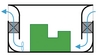
• Cooling air attenuation: inlet and outlet air attenuation baffles can help reduce the noise produced by the cooling air as it moves across the engine and through the radiator. Noise from the movement of cooling air is significant because of the volume required – about 20 cubic metres per second for a generator set with a 50-litre diesel engine. Alternatively, the radiator can be remotely located to a roof, for example, to eliminate this noise source or direct it up and away from people or the property line. Also, making air travel through a 90-degree bend in a duct reduces high-frequency noise (see Figure 4).
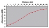
• Maximising distance: when there are no reflecting walls to magnify the noise produced by the generator set, the noise level will decrease by about 6 dB(A) every time the distance is doubled (see Figure 5). If the property line is within the near field of a generator set, however, the noise level may not be predictable. A near-field environment is any location within twice the largest dimension of the noise source (generator set).
• Exhaust silencers: generator sets are almost always equipped with an exhaust silencer (muffler) to limit exhaust noise from the machine. Exhaust silencers come in a wide variety of types, physical arrangements and materials. Silencers are generally grouped into either chamber-type silencers or spiral type devices. The chamber-type devices tend to be more effective, but the spiral-type devices are more compact and may provide sufficient attenuation for many applications. Silencers can be made of cold-rolled steel or stainless steel. Stainless steel is the preferred material for use outdoors when corrosion is a concern. Silencers are available in several different noise-attenuation "grades," commonly referred to as "industrial," "residential" and "critical." Industrial silencers reduce noise by 12 to
18 dB(A); residential silencers reduce noise by 18 to 25 dB(A); and critical silencers reduce noise by 25 to 35 dB(A). In general, the more effective a silencer is at reducing exhaust noise, the greater the level of restriction on the engine exhaust. For long exhaust systems, the piping itself will provide some level of attenuation.
Enclosures
When locating generator sets outdoors, the use of enclosures – particularly sound-attenuating enclosures – combines all of the strategies listed above into a convenient package that provides weather protection as well as sound attenuation.
Steel and aluminium enclosures of all kinds provide at least 10 dB(A) of attenuation for generator sets that must be located outdoors. In many cases, when combined with an effective exhaust silencer, this amount of attenuation may be sufficient to meet many local ordinances in North America and throughout Europe. Standard enclosures are available from most generator set manufacturers and from a variety of third-party providers.
When a greater amount of attenuation is needed to meet local noise ordinances or reduce impact on employees or neighbours, special sound-attenuating enclosures must be employed. In general, the cost of the enclosure is directly related to the level of sound attenuation required. In critical cases, it is not uncommon for the cost of the sound-attenuated enclosure to equal the cost of the generator set itself. Some enclosures also may reduce performance by limiting proper ventilation and load-carrying capacity. Careful design from the outset is important to attain noise control goals while maintaining generator set performance.
Special sound-attenuating enclosures combine both barrier and absorption noise control strategies to contain generator set noise. While both steel and aluminium sound-attenuating enclosures are available, steel – because of its greater mass and stiffness – provides about 2-3 dB(A) better attenuation. Aluminium enclosures are usually only specified in coastal regions where their corrosion resistance is important.


Start early
With maximum noise levels permitted at a property line that range from 52 dB(A) to 72 dB(A), depending on location and zoning, and untreated generator set noise levels that approach 100 dB(A) or more, it is clear that generator set noise mitigation is a subject of great importance. Furthermore, the high cost of retrofitting a site for noise reduction makes it imperative to assess noise performance requirements early in the on-site power system design stage.