UPGRADE & REFURBISHMENT
Stator rewind & conversion to water-cooling adds 55 MVA
8 July 2004How 645 MVA generators at the Big Brown and Monticello coal fired power plant in Texas were upgraded to 700 MVA and performance-enhanced by undertaking a stator rewind and conversion from gas to water cooling.
In October 2000 Alstom was contracted to supply and instal three turbogenerator stator rewind kits for 645 MVA generators at the Big Brown and Monticello coal-fired power plants in Texas, USA. The two plants are, within the meaning of this context, identical in all essentials. The scope of the contract in each case was the same, and covered implemention of the new winding following a thorough inspection, assessment, retightening and testing of the core.
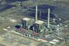
The Big Brown plant (Figure 1) consists of two identical outdoor steam turbine/generator units with a net output of 575 MW each. Units 1 and 2 were placed in service respectively in 1971 and 1972 and burn a combination of PRB western coal and Texas lignite. Each steam turbine had three double shell sections: a single flow high-pressure/intermediate pressure section and two double flow low pressure sections connected to a 645 MVA gas-cooled generator. The scope of the contract was to convert this generator from gas to water cooling while uprating it from 645 to 700 MVA.
Background
A substantial portion of the power produced by owner-operators in the state of Texas comes from nine base load coal-fired units. In anticipation of deregulation and competition, they began a programme to improve the heat rate of these units by replacing specific sections of the steam turbines with high efficiency components using the latest technology in blade design and metallurgy.
At the same steam flow, the higher efficiency turbines not only improved the turbine heat rate, but also produced more power or torque to the generator. The original equipment manufacturer performed engineering studies to determine the capability of the generators and auxiliary equipment to accept the increased output of the turbines.
The OEM study for the Big Brown generators revealed that the existing gas-cooled generator stator would be capable of higher loads only if restored to as-new condition. Even though this had the lowest initial cost, the increased maintenance and end turn vibration issues eliminated this alternative.
After evaluating competitive bids, the owner chose to rewind the generator stator with water-cooled bars. This would also require the installation of a cooling water skid to circulate demineralised water through the generator.
Conversion to water cooling
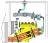
Taking into account project-specific constraints and Alstom’s policy of providing, for retrofit packages, state of the art technology as applied to generators for new power plants, the contractors proposed only one option – a rewind based upon a conversion from direct gas cooling to direct demineralised water cooling for the new stator winding (Figure 2).
The project-specific constraints were:
• An increased turbine power output (around 10%).
• A request from the owner to not increase the generator relative gas pressure (60 psig) in order to preserve the original seal oil rings.
• A request from the owner to preserve the possibility of operating at the original rated power factor and upgraded power output.
• A concern about the magnetic core condition and its ability to run at the higher temperature.
Alstom’s modern technology for generators installed in new power plants features, within this output power range, the following:
• Stainless steel hollow tubes and welded water boxes which eliminate any risk of crevice corrosion and subsequent water micro-leaks.
• ‘Micadur’ (VPI) insulation system
• Radially stiff endwinding supports which are free to expand axially, allowing for flexibility (two shifting) in the power plant operation.
• Concave & convex radial wedging system for stator bars, providing a reserve of elasticity in service, enabling retightening without removing the wedges and eliminating any risk of stator core tooth tip damage during future rewedging.
This technology has been found to ensure high operational availability while minimising maintenance costs.
On this type of generator the cooling gas circulates axially and radially from the opposite turbine side to the turbine side, cooling the magnetic core and the rotor winding. Therefore it is increasing in temperature as it travels along the length of the core, being hottest on the turbine side. The conversion from gas cooling to demineralised water cooling menas that it is possible to cool the stator winding independently of the rest of the generator components.
Ensuring that the cold demineralised water enters the stator winding on the turbine side provides an attenuation of the core temperature in the stator teeth area, is the most stressed area.
Another advantage of independently cooling the stator winding is the increased gas flow available to cool the other components of the generator. The gas originally dedicated to the cooling of the stator winding is now available to cool the rotor winding, the magnetic core, the stepped iron, the phase droppers and the bushing terminals. This cooling is now available to remove the additional heat produced by the increased power output (Table 1). A CAD model was developed to quantify the data in Table 1 and calculate the corresponding temperatures.
Alstom provided some special instrumentation, fitted for long term service, to measure the gas pressure and the lamination surface temperature in key locations around the generator. This enabled fine tuning of the CAD model predictions and the reactive-active capability diagram.
Stainless steel tubes
For the water cooled stator winding stator bars of stainless steel hollow tubes were employed instead of the more commonly used copper hollow conductors.
The literature is full of examples of generators with water cooled stator windings having failed and being rewound well in advance of the usual expected lifetime of a stator winding.
The common cause is, in almost all these examples, has been connected to the presence of copper hollow conductors and a brazed area in contact with water, in paricular:
• Plugging of a hollow conductor.
• Crevice corrosion.
• Leaking of brazed joints.
• Porosity of copper castings.
In most of these cases, in spite of all the diagnostic and on-line monitoring systems developed by the OEMs, the risk of an unscheduled outage remains high.
Leaking water can easily migrate from the endwinding area to the core area with the risk of electrical failure. And a local repair of a leak will not solve the wet involutes problem, and the operation of the generator with poor dielectric characteristics is extremely dangerous.
Alstom’s solution, described below, eliminates the above mentioned root causes:
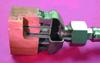
• Use of hollow tubes and TIG welded water boxes made of stainless steel instead of copper and brazed water boxes (eliminating the risk of plugging) (Figure 3).
• No brazing or casting or copper used where it would be in contact with water (eliminating the risk of porosity and crevice corrosion).
• Welding of the stainless steel tubes to the water boxes being accessible during manufacturing (eliminating the risk of water leak).
The oldest turbogenerator using stainless steel tubes and water boxes for a demineralised water cooled stator winding went in operation at AEP’s power plant Amos 3 (WV USA) in 1973, some 28 years ago.
The stainless steel hollow strands are used for the cooling. They do not take part in the line current transportation. The copper plain strands are used for carrying the line current.
Stainless steel is allowing a higher water velocity (up to 2 m/s) without risk of corrosion. The result is an improved cooling and reduced stator bar exhaust water temperature both, average (all hollow tubes) and peak (hottest hollow tube).
The plain strands are made of copper and can be chosen in an optimum way to minimise the eddy currents.
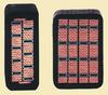
The stator bar design (Figure 5) takes into account as well the need to minimise the differential expansion effect between copper and stainless steel. It shall be noted that no significant difference of thermal expansion coefficient exists between the two materials.
For instance, between 32°F and 212°F (0°C to 100°C), a 40 inch (about 1 metre) piece of stator bar has a copper/stainless steel differential length smaller than 0.4 millionths of an inch (about 10 µ).
Testing of the magnetic core
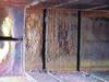
After removal of the stator bars from unit 1, and slot cleaning, instances of damage to the laminations were observed on the opposite side of the turbine, in the stepped iron (Figure 4). It is believed that they were produced by local partial discharges.
An ELCID test (4% flux density) was carried out. Results were within the acceptance criterion. In addition, Alstom recommended the carrying out of a LOOP test (80% flux density) (Table 2) after retightening of the through bolts and construction bolts.
The LOOP test criterion was such that no hot spot temperature should deviate by more than 4K from the local average temperature after 30 minutes heating at 80% flux density.
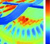
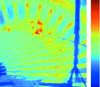
Some local hot spots were identified (Figure 6 ). In addition, an unusual and broader ‘ring shaped’ hot zone was also observed, involving several adjacent packets of laminations on the turbine side. Careful grinding and acid etching were able to clear up the local hot spots. However, the ‘ring shaped’ hot zone condition was not improved.
In order to secure the decision to release the stator core for the rewind, it was decided to conduct an additional LOOP test (Table 3, Figure 7).
The original criterion was modified such that no hot spot should deviate by more than 10K from the local average temperature after temperature stabilisation at 80% flux density. This criterion was defined and experienced as satisfactory by the CEGB (former UK utiility) on some of their fleet which was affected by stator core slackening (CEGB Standard – Site test code n° 12 – Issue 1 March 1980 (Ring flux testing of generator stator cores)).
Although all measured hot spots were within the revised criterion, two of them remained high, close to the acceptance criterion.
A root cause analysis was also conducted. The ‘ring shaped’ hot zone is likely to be due to a combination of insufficient cooling in the radial ducts in its vicinity and core slackening linked with a degradation of the inter lamination insulating varnish. It was noticed that tapered wedges were inserted, in an earlier stage, into some packets in order to restore axial tension between the laminations.
Alstom applied a liquid penetrating resin to the ‘ring shaped’ hot zone concerned in order to stabilise the inter lamination varnish state.
Calculations were also carried out to assess what would be the core average and peak temperatures local to the ‘ring shaped’ hot zone when in service and further assist the decision (Table 4).
They turned out to be in line with commonly used acceptance values and are realistic. The damaged area will take on temperatures which can be accepted as maximum permissible. According to the values shown in Table 4, the re-use of the core could be rated as ‘permissible’.
Risk reduction
The owner released the stator core for rewinding (Figure 8), provided that special instrumentation (thermocouples) was installed to monitor the ‘ring shaped’ hot zone temperatures during and after recommissioning. In addition to the slot thermocouples installed to monitor hot spots during start-up, accelerometers were added to monitor end turn vibration. However, analysis of data collected from these devices has led the owner to conclude that they are not required on future rewinds.
A flux probe was added at the owner’s request, but it is not continuously monitored.
The OEM generator monitoring system was modified to reflect the conversion to water cooling. Table 5 shows the results recorded after the unit was re-commissioned.
New contracts
These retrofits enabled the operators to eradicate generic problems (plugging, porosity, crevice corrosion, water leaks) and increase their unit output, benefits which led to a reduction in the overall maintenance costs and to an availability and efficiency improvement. Two of these units are now out of warranty and all of them are in commercial operation.
The success of the project has led to further contracts – Alstom has been awarded a new contract for Cinergy’s East Bend, Kentucky, plant. The scope includes a rewind of the unit 2 generator, originally supplied by Westinghouse, with conversion to water cooling and an increase in output from 743 MVA to 818 MVA.
TablesTable 4. Expected iron temperatures during operation at full load Table 5. Recorded parameters in service Table 1. Comparison between coolant temperatures Table 2. Results given by the infra red camera during the LOOP test Table 3. Results given by the infra red camera during second LOOP test