Update biomass
UKs model biomass plant gets under way
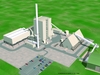
19 July 2006A consortium of Aker Kvaerner and Siemens has secured the contract for turnkey delivery of a biofuel-fired power station for E.On UK in Scotland. Currently under construction, it will be Britain's largest biomass power plant, saving up to 150 000 tons of CO2 emissions per annum, and is expected to be a model for future biomass plants in the UK. Staff report
On the 12th of October 2005 final contracts were signed and E.On UK gave the final go-ahead for its 44 MWe dedicated biomass power plant at Steven’s Croft, near Lockerbie in Scotland. Construction got under way in January with the traditional ground breaking ceremony. About 40 permanent jobs will be created at the Lockerbie site with a further 300 expected (new or preserved) in forestry and farming in the area.
Consortium leader Siemens’ scope includes all civil works on the site, as well as obtaining all building permits and managing the process of obtaining approval from the Scottish Environmental Agency to ensure that a recently constructed local drain system, the Sustained Urban Development System (SUDS), is not negatively affected. In addition to overall co-ordination, engineering and project management the order also covers the supply of the steam turbine power island and all the civil works, erection, and electrical and I & C equipment. Kvaerner Power will supply the power boiler, based on a bubbling fluidised bed combustor, the fuel handling system and the flue gas cleaning plant.
The power island includes the steam turbine, generator, air cooled condenser, transformers, and the required piping network. Siemens PG and Kvaerner will in partnership supply a Siemens PCS7 control system for their respective areas and the interface between the two control systems. All auxiliary buildings will be supplied by Siemens, including an office/control room, a work shop, water tanks and the necessary road networks within the plant.
The power boiler, with steam capacity of 126 MW, is a bubbling fluidised bed type supplying steam for an SST800 steam turbine, which powers an Sgen5-100A-2P generator producing approximately 51 MW. With the electrical house load at approximately 7 MW, this results in a net output of 43.9 MW.
The plant will initially burn forest residue consisting of sawdust, branches and offcuts from a sawmill situated close by. E.On is also hoping that local farmers will switch to producing fast-growing willow which would become part of the fuel mix for the plant.
Contract conditions
The project first started development in January 2003, receiving outline planning permission in July 2004. The Big Lottery Fund, the largest of the UK National Lottery distributors, supported the development with a grant of £18 million from its Bioenergy capital grants scheme. The project contract was signed on October 12, 2005 with an expected duration of 25 months to the end of the reliability testing. Of the total investment of approximately €130 million, Kvaerner’s and Siemens’ shares are each around €50 million. Major work on site began in January. The schedule expects completion of all major foundations by July 2006, backfeed to the main transformer in February 2007, first wood burning in June 2007, sustained steam to the steam turbine in August 2007 and start of reliability tests in October 2007. The final performance test will follow, after whcih the plant will be available for handing over to Eon UK.
Health, safety and environmental considerations have taken a prominent role on this project. Siemens-Kvaerner employed a full time HSE manager immediately after the contract signing date. This has given a “safety culture” to the entire project to ensure complete compliance with strict UK requirements. Siemens-Kvaerner has also agreed that the site will be governed under the rules associated with the UK’s National Agreement for the Engineering Construction Industry.
Biomass burning
The plant will provide a CO2-neutral supply of electricity, which means that during the combustion (of biomass) precisely as much carbon dioxide is released as was removed from the atmosphere during plant growth. In addition to freshly cut wood and seasoned (ie scrap) wood the plant can also fire as fuel different grades of plants, such as willow specially grown for use in power generation. The power plant is still capable of attaining full output when firing such high moisture fuels.
Choices based on fuel type
All aspects of the Lockerbie project are driven by the choice of fuel. Not only is the power plant dimensioned and designed for biofuel, but its location has been carefully chosen in an area with good transport connections and secured long-term fuel availability. The site itself is particularly devoted to forestry related activities.
The wood fuel will be delivered by conveyor to a 10 000 m3 A-frame store with enough capacity for two days at base load operation. The wood will then continue via a conveyor into smaller silos which control the wood flow into Kvaerner’s Hybex boiler.
The 220 000 tonnes of oven-dried fuel required for the station every year will come from the local area, with initial contracts likely to be for forestry residue. It is expected that within four years of operation up to 45 000 (oven-dried) tonnes a year will come from willow harvested by local farmers.
Fluidised bed boiler
The Aker Kvaerner energy-from-waste process is well proven for the combustion of waste, and is said to provide good integrated pollution control and integrated waste management. Fluidised bed boilers are well known for their inherent fuel flexibility compared to other combustion technologies. It is possible to combust fuels with a wide range of calorific values, ash and moisture content.
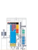
In this plant Kvaerner’s Hybex boiler (Figure 2) will be operated on base load throughout the year. The design is tailored to a moist fuel with a lower calorific value ranging from 9.4 down to 5.3 MJ/kg – the greater part of the fuel will be from fresh green wood sources, such as round wood logs and sawmill residue. In the future up to 20% each of recycled wood and energy crops will be used each year. A power boiler which uses bubbling fluidised bed technology is particularly well suited for this kind of fuel mixture, compared to circulating fluidised bed technology which is better suited to the combustion of dry fuels such as dried biomass or co-fired coal.
Combustion of fuels containing chlorine presents a challenge for the process management. The Lockerbie power boiler will feature austenitic steel superheaters, which enable corrosion to be minimised even when fuels containing chlorine and alkalines are combusted. The fuel is received and stored untreated in a large pile inside the receiving and processing building. After processing it is transferred to an A-frame fuel storage with capacity for 2 days at full load. The fuel is conveyed by belt and drag chain conveyors from the A-frame storage to the boiler’s dosing silos.
Combustion process
In fluidisation combustion conditions solid particles are suspended in an upward moving gas stream so that the gas-solid particle mixture behaves like a fluid. In a bubbling fluidised bed boiler the combustion takes place in a dense fluidised bed at the bottom of the combustion chamber and above the bed. Small fuel particles burn rapidly above the fluidised bed, which is composed of sand, fuel and ash, while larger particles filter into the bed where they are dried and gasified. The residual char is burned mainly in the fluidised bed while volatile material burns both in the bed and directly above it.
The fuel moisture content can vary within the design limits, in this case from 46% up to 65%, without adversely affecting combustion. Attainment of stable combustion with high moisture fuel is due to the high heat capacity of the bed material. The turbulent properties of the bed ensure efficient combustion. The rate of combustion is so high that the steam output can be adjusted by changing the fuel flow according to the load demand. Fuel is fed into the furnace above the fluidised bed through four fuel feed chutes.
The combustion air is staged by utilising fluidising air and overfire air. The fluidising air is introduced into the furnace through the water-cooled ‘hydro beam’ floor (a Kvaerner design innovation) while the staging air, which completes the combustion, is introduced through air openings located on the furnace walls. The boiler is a single drum unit consisting of a furnace and a second and third pass. The furnace and the second pass are of gas-tight, membrane construction. The lower furnace walls are protected with a refractory, which promotes an elevated combustion temperature zone for combusting the high moisture fuel efficiently and protecting the tubes from erosion. The water-cooled design means that only a thin cast refractory is needed. The furnace floor beams are protected by an inactive layer of sand. Coarse material evacuation is facilitated by the hydro beam floor.
This type of floor features an extended free removal area where the coarse material can be evacuated from the bed. It has more than 30% of the total floor area open compared to approximately 1% in a conventional floor design. The coarse material is much easier to take out of the furnace because the floor is open across the whole bed area, which in practice gives full coverage of the furnace bottom. Plant reliability is improved by the water-cooled membrane construction of the air ‘beams’, which have no moving parts and no seals to maintain. This air becomes part of the overall air circulation, ensuring proper cooling even in exceptional conditions.
Power island
The boiler produces steam for the SST800 steam turbine, which powers a 52 MW Sgen5-100A-2P generator. To increase process efficiency, the steam turbine exhaust goes to an air cooled condenser.
The compact power island block comes ready assembled on a standard frame. The generator will be situated on a separate foundation block, a solution that allows for short construction time and a high quality guarantee. In this modular system the turbine/generator is composed of basic modules such as inlet, outlet and extension sections, as well as standardised construction elements such as the bearings, the mechanical parts for the control system, the oil unit and the bearing oil cooling system. The 2-pole generator, which features what Siemens calls ‘maintenance friendly’ brushless excitation, comes with an integrated air/water cooler.
Exhaust steam from the steam turbine is condensed in the air-cooled condenser connected directly to the turbine exhaust. Non-condensable gases are extracted from the exhaust steam by means of a vacuum pump and injectors, and discharged into the atmosphere. The condensate is collected and stored in the main condensate tank and discharged into the deaerator/feedwater storage tank by the main condensate pumps.
Flue gas cleaning system
The combustion flue gases first reach the radiant superheater section in the upper part of the furnace, then the final stage superheater above the nose. In its second pass, the flue gas flows downwards through the primary superheater elements and the first economiser package. After the second pass the flue gas enters the remaining economizer sections in the uppermost part of the third pass. Before leaving the third pass, the flue gas flows across flue gas air preheater sections. After the heat transfer surfaces the flue gas is led to a fabric filter, where ash is separated from the gas. The dust-free flue gas flows through the frequency controlled fans to the stack.
Control
The plant will be controlled by the Siemens PCS7 process control system which is designed for use with industrial turbine-generators in industrial power plants. Operating and monitoring capabilities are provided by PC-based systems with the Windows NT operating system, whcih uses standard Simatic S7 components. The operating and monitoring system is the “window to the process.” From the operator stations, operators and maintenance staff can keep track of the process, change values, and communicate with the process via the automation systems. The operating and monitoring system also confirms receipt of alarm signals and operating orders.