combined cycle
Transforming Tallawarra: GT26 based plant for booming New South Wales
1 March 2007One of a spate of new orders worldwide for GT26-based combined cycle power stations, TRUenergy’s Tallawarra plant is being constructed on the site of a demolished coal fired plant in New South Wales, Australia.
In terms of access to gas supplies as well as to the electricity transmission system, Tallawarra, formerly the site of a 320 MWe coal plant, can be considered one of the best power generation locations in New South Wales, Australia. But the gestation period of the present CCGT project has been quite long, with site ownership changing several times.
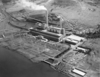
The 600 hectare site, on the shores of Lake Illawarra, 13 km south of Wollongong in New South Wales, was earmarked for redevelopment as a power station site following decommissioning of the old Tallawarra plant in the mid-1990s. The coal fired station operated until 1989.
The new combined cycle plant proposal was initially developed by the then site-owner Pacific Power – one of three state owned generators formed from the restructuring of the NSW electricity industry in the 1990s, prior to the establishment, in 1998, of the Australian National Electricity Market.
The Pacific Power CCGT proposal was the subject of an extensive Environmental Impact Study, completed at the end of 1998, and subsequently was granted development consent by Wollongong City Council. But the project was put on hold because of lack of demand.
In February 2003 the Tallawarra site was bought by TXU from Pacific Power. Then, with Singapore Power’s purchase of TXU Australia in 2004, it became part of Singapore Power’s merchant energy business. In 2005 ownership of the site passed to Hong Kong based CLP through its purchase of assets from Singapore Power. These assets were combined with CLP’s existing Australian power station, Yallourn (1450 MWe, lignite fired), in the Latrobe Valley, Victoria, to form TRUenergy, the current Tallawarra site owner and developer of the combined cycle project. TRUenergy, which is based in Melbourne, has more than 1.1 million gas and electricity customer accounts and in addition to Yallourn also operates the 1280 MWe natural gas fired Torrens Island plant, in South Australia.
Initial site works for the Tallawarra combined cycle plant were carried out in 2004 but it was not until 2006 that the EPC contract was finally placed. The plant is expected to begin commercial operation in autumn of 2008.
The new Tallawarra combined cycle plant represents an investment by TRUenergy of around Aus $350 million, reflecting the company’s confidence in the need for new generating capacity in the growing NSW energy market.
TRUenergy intends it to be a “fast start” plant, capable of responding quickly to peak demands driven by air-conditioning loads on hot days.
The turnkey EPC contract for the 435 MWe Tallawarra plant was won by Alstom, which was also awarded a contract for a 12-year long-term service agreement covering the GT equipment. The two contracts are worth in total around 250 million euros.
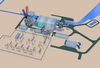
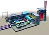
The plant is of the single shaft configuration. The Alstom scope includes design, supply, installation and commissioning of the entire power plant, including GT26 gas turbine, 160 MW steam turbine, condenser, heat recovery steam generator, step-up transformer, plant control systems, civil works and balance of plant.
The placing of the order for Tallawarra came shortly after the award in 2005 to Alstom of turnkey EPC contracts for two GT13E2-based combined cycle contracts in Australia, that for the 450 MW Braemar project in Queensland (3 x GT13E2) and that for the 310 MW Kwinana project in Western Australia (1 x GT13E2).
Tallawarra is one of a succession of recent orders worldwide for the GT24/26 gas turbine following its relaunch in 2002 with a number of modifications and upgrades. There is an existing GT26-based combined cycle plant in Australia, CS Energy’s Swanbank E, which has been in commercial operation since 2002.
The Tallawarra site
Following its retirement in 1989, the old Tallawarra coal-fired station was decommissioned over a 10 year period and demolished to ground level. During the demolition works, the majority of existing pits, trenches and voids were backfilled with crushed concrete rubble. However, asbestos fibres, originating from the old plant, were found in some areas and an extensive asbestos removal plan was therefore needed. Under the plan all potentially contaminated rubble is being removed to an on site repository area, for burial and capping with a visible plastic marker overlaid with clean imported engineered fill.
TRUenergy has excavated to a designated level over the whole plant area and installed a geotextile layer over it, called the “green layer.” On top of this layer about 200 mm of backfill material has been compacted.
The challenge is to design the new plant including all related underground services and deep foundations, pump pits etc in such a way that the green layer is not penetrated.
On the engineering side, the requirement of not disturbing the green layer can complicate what would normally be straightforward design features and call for special solutions. For example, some of the underground drain pipes need to be equipped with pumps (rather than just relying on gravity) as the required slope for the pipes cannot be achieved without excavating below the green layer. Also some pumps need to be designed with a low NPSH (net positive suction head) where there is insufficient depth for pump pits, while some of the foundations on which equipment is placed are above ground.
The new plant makes use of some structures retained from the old station and also has to be constructed in a relatively limited area. This creates further challenges, notably in meeting the requirements of the Building Code of Australia (BCA) in terms of safety distances, vehicular access for fire brigades all around buildings etc. Additional measures on the fire fighting and detection side are also required to meet the BCA.
The terrain to be occupied by the new power plant consists of basically two main plant benches separated by an 8.5m high reinforced concrete retaining wall. The main power island, comprising the power train, HRSG, and transformers as well as auxiliary buildings, such as workshops, store and administration offices, is located on the lower main bench level at +2.8m AHD (Australian Height Datum) formerly supporting the boiler and turbine house of the old plant. The higher bench level, located at about +11m AHD, will accommodate the new water treatment plant and switchyard.
The new combined cycle plant will occupy a small portion of the overall site. and discussions have been held with the local community on the development and possible alternative uses for the surplus land. In September 2006 the Wollongong City Council agreed to allow the assessment of potential new zones on the site.
Cooling water system
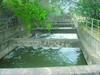
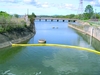
The cooling water inlet and outlet canals of the old plant are being reused, modified in terms of width and depth to accommodate increased flow rate.
The new cooling water screening system and pumping station (with seal pit on the discharge side) will be integrated into existing structures in the middle section of the canal system.
The cooling water system of the new plant had to be adapted to the existing geometry of the canal system. This meant, among other things, that the cooling water pumps for the new plant had to be designed with a low NPSH and the pump rotor frequency had to be lowered to avoid cavitation.
The cooling water is taken from Lake Illawarra, which is brackish, and the steam condensing system is direct water cooled, ie the cooling water runs back to the lake and is not used in a closed cycle with cooling tower.
Any future extension of generating capacity on the site could not make use of the direct cooling water system because the maximum capacity of the existing canal has already been reached. Also, any additional heat load placed on the lake would lead to an excessive increase in its average temperature, with potential effects on marine flora and fauna.
A dyke wall separates the lake from the open sea and a project is underway to connect the lake to the open sea in order to allow water exchange.
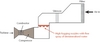
The usual way to avoid micro and macro fouling in a cooling system, especially inside the main condenser, is to apply chemical dosing, consisting of free chlorine and sulphuric acid, but this is not permitted in the case of Lake Illawarra. It has therefore been decided to adopt a “thermal shock” process to control biological growth inside the cooling water system and its equipment. The process entails periodic closure of the cooling water inlet and outlet canals by means of stop locks. The cooling water pumps remain in operation and the warm cooling water coming out of the main condenser is passed through a special bypass pipe to the inlet section of the pumps and cycled through the condenser. In this closed cycle the water heats up, to a temperature of about 42ºC, eliminating the sealife. This system does not require the addition of chemicals and is very efficient, as demonstrated at the Rosarito plant in Mexico.
In terms of capital cost it is however more expensive as it requires a more complex water network. The problem is that the power plant environmental permit only allows it to discharge water into the lake with a delta temperature of 5ºC or less compared with the inlet water (which is at the lake water temperature). As the thermal shock process involves heating the water up to 42º this water cannot be discharged back into the lake without treatment. The solution adopted at Tallawarra is “attemperation pumps”, which pump cold water from the inlet canal to the sealpit in the discharge canal, where the hot water gets mixed with the cold water and the temperature limits can be fulfilled. The temperature is controlled by the mass discharge mass flow and the attemperation water mass flow. As the thermal shock operation requires the plant to be running at less than full load, it most probably will be done during the night, maybe every two to four weeks, depending on the rate of fouling.
Another requirement is that fish must be protected. Fish protection measures consist of the following:
• Installation of a floating barrier wall in Lake Illawarra to prevent jelly fish from being sucked into the power plant’s inlet canal. Jelly fish normally float in the upper 1m of water. The barrier wall therefore has a depth of around 1.2m.
• Provision of a bar screen (coarse rack) right at the water inlet to the canal. This has a width of 120mm, which prevents big fish (and surfers!) swimming into the canal. Once a fish is in the canal it has no chance of swimming back due to the flow velocity.
• A multiple disc screen equipped with buckets filters out all fish, prawns, jelly fish etc and transports them in buckets via a fish returning canal back to the lake. The fish returning canal is a half pipe with mesh protection on top to prevent birds from attacking the fish.
Water is a very scarce resource in Australia so rain water collected at the Tallawarra site is collected and stored in two 1000 m3 tanks and used as raw water for the plant and for fire fighting. The tanks were part of the old plant.
The upgraded GT26 turbine
The GT26 gas turbine employs a range of advanced technologies and materials, including single crystal blading, to achieve a small footprint with high power density. The engine has the same basic size as the medium sized GT13E2 but produces some 100 MW more power. It also offers great operational flexibility with low emissions and the ability to run on a wide range of fuels.
The main technology differentiator is sequential combustion, which has been described as the reheat principle applied to gas turbines.
In 2002, with relaunch of the GT24/GT26 following resolution of issues arising during the early years of operation, the engines benefitted from a significant performance increase thanks to the introduction of an upgraded compressor. Since then, over 30 engines with this higher rating have entered operation and the large numbers of operating hours now accrued have demonstrated the soundness of the improvements, the front-running machines having successfully completed full hot-gas path inspections after more than 23 000 fired hours.
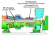
However it was recognised that this upgrade had far from exhausted the potential of the GT26 technology platform. Development continued towards the next evolutionary step in the rating path. Based mainly on a further increase in the mass flow, this new upgrade takes the GT26 another evolutionary step closer to the 60% combined cycle efficiency mark. The primary goal of this latest upgrade is a performance increase in terms of power rating. From the original compressor redesign of 2002, it was known that the capabilities of the compressor were not fully utilised. An additional, although much smaller, increase in mass flow would be possible for a relatively small change to the compressor hardware.
In addition, other improvements arising from the ongoing development programmes have also become available, in particular in the area of better seals, with the object of cutting down the amount of leakage air in the engine.
These two measures – a small compressor mass flow increase and a reduction of leakage air – provided the basis for a further improvement in the rating of the GT26.
The 2005 compressor upgrade is mainly based on a restaggering of the leading blades to increase the mass flow. In addition, to maintain the correct pressure within the compressor at the cooling air bleed points some restagger was also carried out in the mid-section of the compressor. Some blade counts were increased to maintain the correct operation window. However, the actual flow path, as defined by the outer casings and the rotor profile, remained unchanged, so this further upgrade is also fully retrofittable into the earlier engines.
The forecast actual mass flow increase was an additional 1.5% on top of the 2002 compressor redesign. As this is a relatively small amount the corresponding hardware changes are much less than in 2002 and there has been no need to further optimise the exhaust gas housing.
Reduction of leakage air in the engine is the second area that has been addressed in order to improve performance. Here we are talking about leakage of cooling air in the turbine and combustors rather than tip leakage in the blade or vane stages.
The improvements themselves involve either adjustment of seal dimensions, replacing existing seals with seals of more robust design or, in a few cases, adding additional seals. In all cases the intention is to reduce the amount of cooling air that is wasted through leakage and does not contribute to cooling – air that has to be additionally taken from the compressor bleed points. The amount of air used for component cooling remains unchanged and although the total air taken from the compressor is reduced, the cooling effect on components remains unchanged.
As with the previous upgrades, the final validation was done in the GT26 engine at the Alstom test power plant in Birr, Switzerland. After installing the improved components, the actual test campaign commenced with ignition of the gas turbine at the beginning of April 2005. Validation is now complete and the design targets in terms of the performance increase have been met. Taking all these improvements together, ie the increased compressor mass flow and the reduction of leakage air, there is an improvement of 7.3 MW, which brings the GT26 ISO rating up from 281 MW to 288.3 MW.
This upgraded version of the GT26 is the machine that will be installed at Tallawarra.
The plant will also be equipped with high fogging and evaporative cooling. Evaporative cooling involves the introduction of water into the air entering the gas turbine compressor and cooling this air by enthalpy reduction through the evaporation energy of the water. The distribution manifold wets the medium by spraying the water through nozzles onto a deflector shield. A small percentage of water pumped to the medium is evaporated. The remainder flows through the medium and back to the sump tank. The pump continually recirculates water to the medium. This cooled air results in a higher compressor intake mass flow due to the higher air density, which finally results in a higher gas turbine power output and efficiency.
High fogging provides further augmentation of the gas turbine power by using water injection to cool the inlet air. The high fogging system at the air intake manifold injects small water droplets (droplet diameters of less than 50 microns) into the air through nozzles to over-saturate the air. These droplets evaporate inside the compressor as the air is heated up during compression. The power of the gas turbine is increased by intercooling the air in the compressor, which reduces the work required for compression and increasing the air mass flow.
In the Tallawarra project, high fogging is combined with evaporative cooling (to saturate the air) in the air intake filter house in order to further increase the degree of power augmentation.
Other features
Tallawarra will feature Alstom’s OCC triple-pressure reheat heat recovery steam generator, designed for operational flexibility and daily cycling service, the OCC standing for Optimised for Cycling and Constructibility.
OCC HRSGs (of which there are now more than 100 in service worldwide) feature single-row harp construction, offering pressure parts with unprecedented flexibility and fatigue tolerance under frequent startup and shutdown conditions. Other design features of the OCC HRSG include seamless tubes, full penetration welds and generous use of high alloy materials in superheaters and reheaters to ensure minimal creep life usage in high temperature parts over the life of the HRSG. Among the benefits of the design are improved performance, better economics and optimised fabrication/construction practices.
Another feature of the plant will be the AMODIS modular PC-based plant monitoring and diagnostic system.
This monitoring and information system is comprised of several modules for each main power plant component and for the power plant overall. It covers both local-to-plant monitoring and remote-from-plant monitoring.
At the heart of AMODIS is a PC-based platform using a real-time database. Data is supplied to the platform from the power plant distributed control system (DCS) or from additional instrumentation supplied with some modules. A number of modules then continuously perform calculations on the incoming data to provide information about specific areas of the plant and return these results to the platform to allow them to be displayed for interpretation.
Benefits of AMODIS include: minimising risk of unplanned shut-downs and extension of equipment overall lifetime; increased availability; optimisation of asset performance; plant-wide monitoring coverage with the one system rather than individual systems for each component/function; capability to be tailored to specific plant and operator needs; and utilisation of OEM knowledge.
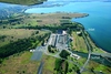
Cutaway Site plan of the Tallawarra combined cycle plant As it was: the old Tallawarra coal plant. This ceased operation in 1989 and was subsequently demolished As it is: photo of Tallawarra combined cycle plant under construction, 16 February 2007 Recent aerial shot, with site work underway for the new plant Existing cooling water inlet Existing cooling water outlet Work underway on the central section of original cooling water system, where the new pump station will be installed Summary of the latest upgrades to the GT26 gas turbine High fogging Evaporative cooling