MEETING THE ATEX DIRECTIVE
Explosion of interest in CFD for the modelling of gas turbine enclosures
8 April 2004The full implementation of the ATEX (Atmosphere Explosive) Directive across the EU has made compliance for proposed plant modifications or new plant construction a matter of great concern to business. With penalties for non-compliance, it is not an issue that can afford to be ignored. But how best can businesses demonstrate with confidence that they have taken the necessary steps? Computational fluid dynamics can assist in providing a solution for operators of industrial gas turbines.
The ATEX Directive is one of a series of new measures introduced under article100a of the Treaty of Rome. The effect of the directive has been to introduce identical requirements for the safety of equipment for use in explosive atmospheres in every country within the EU. The ATEX Directive is important because, unlike the previous European directives concerning hazardous areas, it is a 'New Approach Directive' and is thus mandatory rather than advisory. Besides considering potentially explosive concentrations of gas, vapour or mist in the air, the ATEX Directive also now takes into account potentially explosive concentrations of dust in the air. Furthermore, the sources of ignition covered by the directive have been expanded to cover both electrical and mechanical sources of ignition. Any control equipment that is used to ensure the safe operation of equipment in a hazardous area also comes within the scope of this directive.
There are in fact two ATEX directives, ATEX-100A (94/9/EC) concerns equipment and protective systems for use in potentially explosive atmospheres and ATEX-137A (1999/92/EC) is about the safety and health of workers potentially at risk from exposure to explosive atmospheres. Both Directives came fully into being on 1 March 1996, with a transitional period that ended on 30 June 2003. From 1 July 2003, all new equipment within the scope of the Directive must carry the CE mark and comply with the directive's requirements. Workplaces already in use before July 2003 but modified before July 2006 must meet requirements from the time the modification takes place. From 1 July 2006, all relevant workplaces must comply with the ATEX directives.
Guidance for the UK
The 'UK dangerous substances and explosive atmospheres regulations (DSEAR) 2002' and 'Equipment and protective systems for use in potentially explosive atmospheres regulations' provide a UK legislative framework for the implementation of ATEX Directives ATEX-137A and ATEX100A respectively. HSE (Health and Safety Executive) Guidance Note PM84: ‘Control of safety risks for gas turbines used for power generation’, is the most pertinent set of current guidelines covering the design and operation of gas turbine installations. They make specific and practical recommendations with regard to operational functions such as alarm and engine trip conditions, and the maximum acceptable volume of clouds of explosive mixtures of gas and air. Although it is not a specific legislative requirement to comply with these guidelines, they provide plant operators and local HSE inspectors with a framework for assessing whether operation of a plant is satisfactory from a general health and safety standpoint. It is therefore appropriate for installations to adhere to the guidelines so far as is reasonably practicable.
Power plant installations commonly involve the housing of the gas turbine generator unit within a confined acoustic enclosure designed to attenuate noise levels as well as providing ventilation for controlled convective heat rejection and gas fuel leak dilution. The potential for fuel leakage means that such enclosures are covered by the ATEX Directive and PM84. In the detection of gas leaks it is important to balance the ventilation system so that leaks can be diluted and removed from the enclosure preventing build up to explosive levels but that dilution is not so great that the true leak magnitude is masked at the detection point. The philosophy is that leaks that cannot be detected are diluted and those which cannot be diluted are detected.
PM84 says that the size of the 50%LEL (lower explosive limit) gas cloud before detection must be less than 0.1% of the net enclosure volume, where 100%LEL represents the fuel air mixture just rich enough to be ignitable. In this way a degree of conservatism is built into the criterion. Additionally PM84 requires that the sensor alarm threshold be set at "ideally less than 5% and no more than 10%LEL" and that these detectors should be positioned in the exhaust ducting at positions where the mixing is adequate.
How CFD
can help
In order to establish the thermal distribution within the enclosure airspace and potential gas fuel leak distributions and concentrations, it is important to be able to examine the through-flow inside the enclosure. In situ testing within gas turbine enclosures (anemometer and smoke bomb tests for example) does provide a means of providing overall flow patternation inside the enclosure, however, the results are either qualitative, cold flow based or provide only highly localised information. This is mainly because personnel access is highly restricted when the engine is running for safety reasons. In any instance, however, gas cloud sizes cannot be easily quantified by in situ testing as part of leak studies for comparison to the criterion in PM84.
CFD (computational fluid dynamics) is a powerful predictive computer modelling tool that is able to overcome these restrictions and has been used successfully to investigate ventilation flow characteristics within such gas turbine enclosures. Parameters such as the ventilation flow distribution, flow velocities, local air temperature and gas concentrations can all be evaluated quantitatively at any point within the enclosure from a computer model representative of the plant. This means that a whole host of operating conditions such as emergency shutdown, cold engine and a worst case (largest leak rates, worst leak position and orientation) can all be examined in great detail remotely, safely and at low cost relative to experimental testing. Additionally, hot to cold comparative CFD studies have shown that there is a large effect of buoyancy forces (established from engine casing heat rejection) on the internal flow distribution, that can render many conclusions from in situ cold flow testing inapplicable to hot engine cases.
CFD has a powerful capability to model gas leaks in enclosures. The HSE guidelines (document PM84) state that CFD is the best tool for predicting ventilation and gas leakage in larger enclosures, due to its capacity to allow quantitative assessment against the criterion, and because it enables the modelling, analysis and understanding of design impact before changes are made, or a plant is even built.
Case study
This ability of CFD was put to the test in a recent case study, completed by Fluent Europe Ltd, to investigate the conformance to the revised PM84 guidelines at a particular power plant site in the UK. This was a consequence of changes in the ventilation system occurring after 1 July 2003.
First, a representative model of the inside of the enclosure was built using the company's CFD preprocessor GAMBIT, Figure 1. The gas turbine, intake, diffuser, pipework and enclosure walls are all represented realistically in order to provide as accurate a solution as possible. A series of outlet ventilation ports are positioned on the roof incorporating extraction fans that establish a negative gauge pressure inside the enclosure. The supply is from a number of inlet vents positioned strategically on the side walls. Notice the complexity of pipework around the engine that could restrict ventilation penetration into the gas fuel manifold area. A mesh was applied to the numerical domain as part of the requirements for the CFD calculation, constituting a total of about 3.1 million cells.
The level of heat rejected from the engine casing was calculated from a heat balance across the engine and applied realistically to the casing surface on the model. The commercially available CFD software FLUENT was used to perform the calculations and, in conjunction with site measurements of internal pressure and temperature, was used initially to establish confidence in a baseline operating case prior to leak introduction. Key flow features such as areas of flow stagnation, depth of penetration from the ventilation inlets and temperature distributions around the engine were identified. The variation in average to peak static temperature variations at the exit planes was also identified.
For the safety case, a range of leak source flow rates, directions and locations were modelled in an attempt to create the largest leak cloud possible. The leak flow rates were modelled based on the detector alarm threshold levels in the 3-10%LEL range. A more sensitive setting for the exit sensor would obviously result in an earlier detection and consequently a smaller gas cloud at the point of detection. The leaks were modelled one at a time with the sources located on the underside of the turbine region where the gas fuel rings are positioned and the distance to the exit vents is largest, the air temperature is high and the diluting ventilation flow has restricted access. Additionally, predicted regions of relatively high ventilation air residence time and low local air velocity were used to assist in placement of the leak sources in their worst possible position. A two species mixture model was used to examine diffusion of the gases and a subroutine was written to calculate the sizes of the gas clouds.
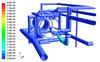
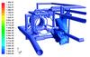
The sizes of the steady state 50%LEL gas clouds for the worst leak case considered were predicted at the 3, 5 and 10%LEL detection levels. These were determined to be 0.083% and 1.61% of the net enclosure volume for the first and last cases respectively. Figures 2 and 3 show the sizes that the 50%LEL gas clouds would reach before they were detected depending on the exit detection levels for this worst considered leak case.
In this instance, it was decided to install detection capable of reaching the 3%LEL level rather than using a less sensitive limit coupled with localised dilution or ventilation system modifications. Detection at the 3%LEL level ensured compliance with the PM84 guidelines in that the cloud size was <0.1% of the net enclosure volume. An analysis of the fuel-air mixture at the exit plane was also conducted to determine the level of mixing and assist in determining a desirable pick up point for the sensors.
This case study showed the importance of using CFD for quantitative evaluation of potential gas fuel leakages and enabling an informed decision to be made on compliance with the new ATEX Directives that are now in force.
More information on the ATEX Directives can be found from the European Union website at http://europa.eu.int/comm/enterprise/atex/