TRANSMISSION & DISTRIBUTION
IEC 61850 cuts out substation confusion
8 April 2004By enabling interoperability of devices, IEC 61850-compatible substation automation devices can minimise the installation of inter-system gateways and protect an investment against changes in communication technology or incompatibility among different manufacturers’ systems.
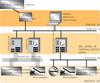
The service life of substation primary equipment, such as circuit breakers, is about 40 years, while that of secondary equipment, such as automation systems, is about 15 years. Substation automation typically comprises three hierarchical levels: the station level, the bay level and the process level, as shown in Figure 1. Often in the USA only the station level and the control/protection level are found. Communication is playing an increasingly important role in substation automation systems, and has been undergoing technological changes in the last few decades. Devices of different generations are hence often incompatible because the protocols are not the same.
Another dimension of interoperability is related to the communication of equipment from different manufacturers. In the USA and in Asia, it is common to find devices from a variety of manufacturers in a substation. The two main reasons are:
• a single manufacturer may not be able to supply the full range of devices needed
• two protection systems from different manufacturers are required for one feeder.
In any of these situations, devices need to talk to each other, or to a device they have in common such as a bay controller. When devices use different protocols, gateways can make interoperability possible. In one of the substations of American Electric Power, about 45 gateways have been installed. Gateways make the automation systems costly, and incur much testing on the automation functions involved. They also introduce delays and possibly errors in communication.
IEC 61850
In the early 1990s, parallel developments were taking part in Europe and in the USA. The IEC identified the need for a standard interface for the new "Intelligent Electronic Devices” (IEDs) that were emanating from the different manufacturers. An IED is any device incorporating one or more processors, with the capability of receiving, or sending, data/control from, or to, an external source.
Examples are digital relays and controllers. Technical Committees TC57 and TC95 set up a joint working group which developed a standard (IEC 60870-5-103) for the "Informative interface of protection equipment".
In the US, a project called Utility Comm-
unications Architecture (UCA) was carried out by the Electric Power Research Institute to develop a common infrastructure for real-time utility communications across the utility enterprise. That part of the work on the communications within a substation became UCA 2.0.
In 1995 the IEC recognised the need for a more general standard covering communications networks and systems in substations, and set up new working groups under Technical Committee TC57. The working groups were:
•WG10: Functional architecture and general requirements
• WG11: Communication within and between unit and station level
• WG12: Communication within and between process and unit level.
These three working groups brought together experts from many countries – with experiences of both the IEC 60870 series of protocols and UCA 2.0.
It soon became obvious that the three IEC working groups were developing what would become the IEC 61850 standard at the same time that EPRI was developing its UCA 2.0 definitions. To enable UCA 2.0 to reach a wider audience, EPRI planned to have the documents published by the IEEE. To prevent these two definitions of substation communication from competing against each other on the world market, it was concluded that the activities of IEC and EPRI should be harmonised to arrive at a single world-wide accepted standard. IEC 61850 “Communication networks and systems in substations” is the result.
Main features of the IEC standard
The use of one communication standard would clearly lead to the end of the present cocktail of protocols in substations. During the preparation, care was also taken to ensure that the standard would be future-proof. The following three typical parts of an automation system were considered:
• data of functions
• services
• communication protocols.
The functions in question are protection functions, control functions, monitoring functions and so on. A service is how data of a function are transmitted, and different data require different services. For example, the large quantity of data from a fault recorder is transmitted in the form of a file transfer. A trip signal is transmitted by means of a service which takes the shortest possible time. Services such as these are provided by the communication protocols.
Unfortunately, in most of the other existing standards, the data of the functions, the services and the communication protocols are all mixed together. For example, ‘circuit breaker in the ON state’ is a report from a circuit breaker function to the human-machine interface. Existing standards define specific bit-sequences for these messages. Bit-sequences are protocol-dependent and protocol is technology-dependent. If communication technology changes, the bit-sequences would need to be adjusted accordingly.
But it is not desirable to have a new communication standard, or replace a substation automation system completely, whenever the communication technology changes. IEC 61850 addresses this issue by separating the data of the functions, services and communication protocols. Functions and services hardly change with time. The overcurrent protection function for example has not changed for decades. The standard contains the data models of all the possible functions in substations, and standardises the names of these functions and their data. For example, the name of the ‘time-overcurrent protection’ function is PTOC. ‘Circuit breaker’ is also a function and its name is XCBR. A data model is a set of data belonging to a function. For example, the data model of a circuit breaker includes:
• Mode, i.e. enabled, blocked, disabled, under test etc.
• name plate, i.e. the technical details of the switch controller
• position, ie open, closed, intermediate etc.
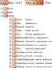
Figure 2 shows the Explorer layout for these and other data belonging to the circuit breaker function. Most substations have more than one circuit breaker and the final data name comprises the standardised parts and user-specified parts. The latter parts allow the utility to distinguish one circuit breaker from another. In the standard, the standardised function names such as PTOC and XCBR are called logical nodes. There are approximately 90 logical nodes, covering functions such as switchgear, protection, measurement and so on.
The standard also specifies a set of services which cover all the data transfers required within a substation. The services include secure transfer of large blocks of data for reporting purposes and fast transfer of small data blocks such as trip data.
The standard maps these abstract services and the standardised data onto real protocols. These real protocols are Ethernet, Transmission Control Protocol/Internet Protocol (TCP/IP) and Manufacturing Message Specification (MMS). When communication technology changes, it is necessary only to map the abstract services and the standardised data to the new protocols.
Rules are included in the standard to allow new logical nodes to be added. The principle behind IEC 61850 for standardising communications is applicable not only to the substation environment, but also to other electrical industries.
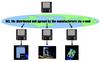
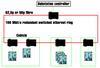
The functions reside in IEDs. An IED may house one or more functions which exchange data over the Ethernet. 100 Mbit/s Ethernet is expected to be the ‘norm’, but slower networks may be used in less demanding substations. Figure 3 shows a 100 Mbit/s switched Ethernet arranged in a open ring. The IEDs are connected to the switches.
Utilities expect ‘gateway-free’ access to all intelligent components of the substation automation system by means of the commercially available tools and standard communication protocols. These requirements demand a flexible bus at all levels. The use of Ethernet technology fulfils these requirements and provides a uniform access to the data throughout the whole substation. Ethernet is the only system whose present version is compatible with its original version invented in the 1970s, and over 95% of
office networks are Ethernet.
The information exchanged between devices includes operational information and configuration information. Operational information, such as status and control, is standardised and of medium priority. Configuration information, such as file transfer and changing settings, is of low priority. Processes add two further very demanding kinds of data transfer: the transfer of sampled values and of protection signals.
The fourteen parts of the standard are shown in Figure 4. Ten parts are already international standard, and the remainder are expected to become so in the coming months. Manufacturers have developed, and in 2004 will launch, their products compliant with IEC 61850.
Substation configuration language
With IEC 61850, a utility or system integrator may need to integrate into its system IEDs from another manufacturer. Such a user needs to know, system-wide, precisely:
• which devices offer data
• which devices need data
• what these data are
• the services required to transfer the data.
It needs to find out such information for the devices to be integrated, and such information comes only from the manufacturer of these devices. IEC61850 facilitates the engineering work in two ways:
• Each device can implement self-describing communication functions, which allow its configuration to be queried in a standardised way.
• The ‘substation configuration description language’ (SCL) makes it possible to describe, in a standardised way, the functional and communication capability of devices, their configuration, a concrete communication of a substation automation system, and the allocation of devices to the substation primary equipment. This description can be exchanged between engineering tools of different manufacturers.
The configuration of the entire substation and its IEDs is described in configuration description files. These files not only make it possible to build up the automation system, but also allow one to be specified. All the information involved is standardised by SCL, and written in the ‘extensible markup language’ (XML).
Relation to UCA 2.0
The basis and the method of standardising substation communications in IEC 61850 are new. The nearest relatives of IEC 61850 are IEC 60870-5 and UCA 2.0. IEC 61850 adopts, from UCA 2.0, principles such as object-oriented approach, TCP/IP and Ethernet. It built on IEC’s experience in digital communication in substations. Furthermore, IEC 61850 takes into account the requirements of substation automation worldwide.
A few manufacturers and utilities are now supporting IEEE Technical Report UCA 2.0, which was published in 1999. But there is an international agreement that, for substation communications, there shall be only one standard and this is IEC 61850. Utilities and manufacturers using UCA 2.0 are migrating, and will migrate, to IEC 61850.
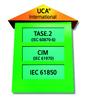
It has also been agreed that the name UCA is now only an umbrella term embracing IEC 61850, common information model (CIM) and IEC 60870-6 telecontrol application service element.2 (TASE.2), as shown in Figure 5.
Demonstrations and tests
Since standardisation work got underway there has been interest in demonstrating the viability of substation automation systems based on the principles of IEC 61850 and in using practical results as guidelines for the standardisation work. The following are some of these demonstrations and tests:
• Interoperability ‘Bay devices and station controller’, Germany, 1998-2000
• Interoperability ‘Between bay devices’, Canada, 2001
• Interoperability ‘Sampled values’, USA, 2002
• Interoperability ‘Trips and sampled values’, USA, 2002
• Interoperability ‘Between bay devices’ and manufacturer-independent engineering data exchange
•Germany, 2002
•USA, 2003
•Further projects 2003-4
• Interoperability ‘Between bay devices and substation controller’, and manufacturer-independent engineering data exchange, 2003-beginning of 2004.
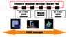
One of the tests was performed in Berlin at the end of 2002, combining protection devices from ABB, Astom and Siemens in the test configuration shown in Figure 6. Unlike earlier test series, this interoperability test was conducted in equivalent real-life situations, including in particular degraded and unfavourable ones, to prove selectivity, security and quality. Engineering on the devices of the three manufacturers was done using the substation configuration language (SCL) via e-mail, as shown in Figure 7. Generic Object-Oriented Substation Event (GOOSE) messages are fast multicast messages on the Ethernet for time-critical events such as tripping a circuit breaker.
The test was very successful. It proved interoperability and the possibility of easy engineering. The manufacturers plugged their devices together and immediately the system started running. This suggests fast installation and commissioning owing to manufacturer-independent engineering data exchange based on IEC 61850-6. The key objective of checking the validity of the standard was fulfilled, and the experience gained was used immediately to improve the specification. This has helped speed up the completion of the standard and achieve high quality content.
Further tests were performed at the end of 2003 to verify commands, reports and engineering data exchange.
Benefits to utilities
The major advantages of IEC 61850 are the interoperability of IEDs of different manufacturers, and the fact of being the only globally accepted standard, bringing benefits to the utilities as well as manufacturers.
The use of Ethernet communications for all the substation automation functions allows for standard and simpler cabling in comparison with the use of parallel communications. This is a definite advantage in project execution, equipment installation and equipment testing.
Ethernet is highly backward-and-forward compatible. For example, a 10 Mbit/s network can easily be integrated into a 100 Mbit/s network, and a 100 Mbit/s network can be integrated into a 1 Gbit/s network in the same manner. Thus the investment of the utility is safeguarded.
The manufacturer-independent engineering data exchange defined by the IEC standard will reduce project time and facilitate engineering and maintenance. It will also reduce training efforts.
The capability of industrial Ethernet components is expected to increase every year, and it will be possible in a few years time for the utility to have one single communication infrastructure, streamlining the flow of data within the organisation.
Because IEC 61850 specifies open and common protocols such as TCP/IP, access to public and private data networks is easy. It opens the possibilities of remote interrogation of substation equipment, alleviating maintenance and reducing the number of site visits.
The investment of the utility is safeguarded because the development of the communication network is independent of the development of the applications. The utility may also
benefit from the latest communication technologies to enhance the performance of the control and protection system.
IEC 61850 does not make the use of the station bus or the process bus mandatory. The number of buses is flexible. It is not necessary to adopt a rigid two-level or three-level structure (station level, control/protection level and process level). The utility will find it flexible enough to configure its system.
So the utility will find its operation more streamlined, its investment is better guaranteed against technological changes and staff can run the automation system more efficiently because there are fewer variations.
Current progress
When replacing substation automation equipment utilities must bear a high expenditure because of the incompatibility of devices from different generations of communication technology. IEC 61850 can safeguard such investment against changes in communication technology.
The standard is completed and over 20 manufacturers are developing products compliant with IEC 61850. Manufacturers and utilities have carried out many tests to confirm the viability of the ideas in the standard documents. The interoperability of substation automation equipment of different manufacturers has also been demonstrated. The first commercial products compliant with IEC 61850 are starting to become available during 2004.
TablesFigure 4. IEC 61850 documention