turbine developmentS
Ireland hosts first 50 Hz HEAT ST
31 July 2006The first 50 Hz version of GE's HEAT* steam turbine is now in commercial operation. Innovations in this new steam turbine include a reaction HP turbine capable of 2400 psi and a stainless steel 48in last stage bucket – the first axial exhaust application of this bucket – with 3D aerodynamics and curved–axial entry bucket attachments.
The 50 Hz launch unit of GE's new
HEAT (High Efficiency Advanced Technology) steam turbine, at Tynagh Energy Ltd's combined cycle power plant in County Galway, Ireland, was synchronised to the grid in January 2006 and commissioning was completed in March – a construction period of only 24 months, from release to commercial operation. This follows the successful
introduction of the 60 Hz version into the US market in late 2005, with entry into commercial operation of the SCPPA Magnolia CCGT plant in Burbank, CA, followed by the SRP Santan Expansion CCGT plant in Gilbert, AZ.
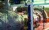
Full scale validation of the 50 Hz HEAT machine was integrated into the installation and commercial acceptance testing of the 400 MW Tynagh facility. The plant has a one-on-one multi-shaft configuration. On one shaft is a GE FA gas turbine, with HRSG, driving a GE 324 hydrogen cooled generator. On a second shaft is the HEAT steam turbine (supplied with steam from the HRSG) driving a GE 9A5 air cooled generator.
The environmentally sensitive Tynagh power plant, which includes advanced noise attenuation measures, was supplied by a consortium of GE and Gama Power Systems Equipment.
It will supply up to 9% of Ireland's electricity requirements.
The second 50 Hz HEAT turbine is being installed in Italy, while two more are on order for a Spanish power plant.
The HEAT concept aims to meet the combined cycle operator’s need for operational flexibility coupled with high efficiency. HEAT addresses these requirements through:
• Higher initial steam pressures to improve combined cycle efficiency. Extra pressure capability can also be used as additional flow capacity to handle heat recovery steam generator (HRSG) duct auxiliary firing.
• Longer last stage buckets (LSB) to reduce the exhaust loss of the steam as it leaves the LP turbine, improving the overall cycle efficiency.
• Optimised clearances in the turbine to improve start-up robustness and steam turbine efficiency.
• A fully automated advanced steam turbine
control system for improved operational flexibility, and reduced start-up times.
The 50 Hz HEAT, designated A15, is a reheat combined cycle steam turbine optimised for application in a 109FB power plant (a one-on-one configuration with a single 9FB gas turbine and a single steam turbine), but also applicable with an FA gas turbine, as the Tynagh plant demonstrates.
The A15 steam turbine is capable of greater than 205 MW when auxiliary HRSG duct firing is in operation.
Advanced features
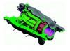
The A15 steam turbine consists of a separate HP turbine section and a combined IP/LP section, which features a single-flow LP in an axial exhaust configuration.
The generator is connected at the HP end of the steam turbine.
The overall arrangement of the A15 steam turbine is similar to other single-flow machines, with the opposed-flow of HP v IP/LP sections, but numerous advanced features have been incorporated.
The configuration of the HEAT turbine uses a fixed mid standard between the HP and IP turbines. During thermal transients, the HP turbine grows toward the generator, and the IP/LP turbine grows towards the condenser. This configuration allows the axial clearances between rotor and stator to be minimised throughout the machine because the rotating and stationary pieces are anchored at the same points.
The shells are supported on the front and mid standards using a centreline support approach. The interfaces between standards and shells are done at the centreline of the machine, which minimises the impact of thermal transients on radial clearances in standards and shells.
Developed over the past four years, the HEAT steam turbine represents a step change in product technology and engineering capability over past GE steam turbines.
The HP section efficiency is optimised with high reaction blading and drum rotor construction. Advantages of this configuration include reduced inner root diameter, advantageous aspect ratios for both buckets and nozzles, and increased stage count for optimum stage energy distribution. The net result is improved power density and overall steam turbine efficiency.
Smaller combined cycle steam turbines (ie plants with only one gas turbine) typically see relatively small throttle steam volume flows. This characteristic leads to turbine designs with short blade lengths and small steam path root diameters, which creates design challenges in balancing robust mechanical design with the maintenance of high efficiency.
For small throttle steam volume flows, the steam path flow passing areas are correspondingly small. Thus, inner root diameters are driven smaller to keep active lengths of buckets and nozzles as large as possible, while maintaining required total flow area. The limiting design parameter then becomes the rotor shaft diameter under the nozzle diaphragm packing. As this diameter is reduced, the rotor flexibility increases, causing rotordynamic and clearance control concerns.
The drum rotor construction with high reaction blading allows the steam path diameter to be reduced and rotor shaft diameter to be maintained for good rotordynamics and clearance control. The reduced rotor flexibility also allows for higher stage counts, which help to achieve higher efficiency.
In order to maintain efficient bucket and nozzle sealing, integral covers are used throughout the HP turbine section. This allows continuous circumferential sealing and multiple seal teeth at each stage.
An added benefit of integral cover geometry is improved steam path quality. Fillet sizes have been minimised, surface finish improved, trailing edges optimised, and throat areas controlled to enhance steam flow characteristics.
The ability to maintain radial clearances is a critical factor in achieving optimum performance for both impulse and reaction style turbines. However, radial clearances in a reaction style turbine become even more critical due to the stage pressure drop distribution and increased number of stages. The opportunity for leakage and the number of sealing locations is greatly increased in the reaction style turbine. To address this, an advanced abradable coating has been developed and applied throughout the HEAT HP turbine section (building on aviation gas turbine technology).
The steam environment posed unique challenges that required evaluation of many different coating compositions. The selected abradable material was validated by component testing prior to incorporation into the design.
At the nozzle airfoil tips the sealing solution proved to be inserted strip seals on the rotor surface.
The strip seals are caulked in place and provide the sealing feature that runs against abradable coating applied to the nozzle carrier inner diameters. Part of the development effort to ensure robust performance of these seals was gaining an understanding of the thermal conductance behaviour of various material combinations.
Seal materials where tested for various incursion and feed rates into the abradable coating material. The final selection was based on the ability to: withstand stage pressure drop; cut abradable coating without damage to the tooth tip geometry; long term durability in a steam environment; manufacturability; and conductance.
The improved inlet and exhaust geometries of the A15 HEAT turbines provide several performance benefits, including: reduced pressure drop; symmetric heating and cooling of the shell structure; improved circumferential flow distribution; reduced dynamic loading on first stage nozzle and bucket.
Dual inlets provide significant advantages in terms of steam flow in the first stage nozzle. For the dual inlet, the difference in flow through the nozzle passages is reduced by roughly a factor of two. This is reflected in reduced inlet pressure drop and a more symmetric flow into the HP turbine section.
In addition to upper and lower inlets, a centreline offset has also been added to the A15 HP turbine inlet geometry. The effect of this feature is to induce a swirl into the inlet steam flow to maintain stable inlet plenum flow over a range of operating conditions. This improves pressure drop and first stage nozzle incidence angle, thus minimising inlet plenum and first stage nozzle losses.
Similar analysis and design effort has been applied to the exhaust geometries.
The structural backbone of the HP turbine configuration is a double shell design leveraging existing steam turbine and H System technology. This structure allows increased pressure capability and improved internal steam path clearance management.
The dual carrier design of the A15 allows operating conditions in excess of 165 bar (2400 psi), with the inner carriers designed to minimise thermal distortion during startup and shutdown.
Centreline supports and false flanges contribute to the symmetric thermal behaviour of both inlet and exhaust carriers. Since the inner surfaces of the carriers form the sealing surfaces of the steam path, understanding and control of thermal distortion, and its effect on bucket/nozzle tips, allows tighter radial clearance during operation.
The IP turbine section uses traditional wheel and diaphragm construction. Integral covered buckets (ICBs) were included for enhanced sealing and efficiency. Tip sealing is achieved by integral teeth and a high/low labyrinth arrangement at the diaphragm outer diameters. A high efficiency reaction steam path (similar to the HP turbine) was used, but with wheel and diaphragm construction.
Upper and lower IP turbine inlets provide thermal symmetry, similar to the HP turbine. The symmetry is designed to minimise thermal distortion during operation.
Offset inlets (as in the HP turbine) were also used at the IP turbine inlet to ensure stable plenum flow across the load range.
The LP turbine section features an improved exhaust hood, a new steam path using an advanced last stage bucket (LSB), and an extended diffuser cone to increase output from the last stage. The LP turbine steam path was designed with ICBs throughout, for improved bucket tip sealing.
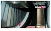
The exhaust hood includes an innovative sliding technology (patent pending), allowing the IP/LP turbine to grow thermally towards the condenser. The aerodynamics of the hood are also improved, with the use of a smaller number of optimised struts compared with previous designs. The mechanical stiffness of the hood is increased as the bearing load is transmitted downwards through the sliding foot into the foundation. This provides better rotordynamic performance.
LP admission pipes are connected at both the upper and lower vertical joint for thermal symmetry for better IP/LP turbine shell thermal transient behaviour.
The steam turbine turning gear is located in the LP turbine hood. Specifically, it is inside the bearing enclosure, and drives through an over-running clutch, to the aft end of the turbine rotor. The entire turning gear is contained within the bearing oil environment and is kept slightly below atmospheric pressure by the lube oil system. The LP turbine bearing location was chosen to allow a common turning gear configuration between the single- and multi-shaft plant arrangements.
GE's newest and largest full-speed last stage bucket was included in the A15 design. Important features of this 1.21 m (48 in) bucket include a curved axial entry dovetail to enable optimum placement of the airfoil on the dovetail, and continuous coupling at the bucket mid span and tip. A 1.07 m (42 in) LSB can also be incorporated into the A15 turbine for higher exhaust backpressure applications.
An advanced control system, with enhanced monitoring instrumentation, enables true “one-button-start” capability while minimising start times and protecting the turbine from possible balance of plant issues. The steam turbine control system also includes enhanced operator messaging for each phase of operation.
Field validation testing
The A15 HEAT steam turbine launch unit at Tynagh was thoroughly validated through a comprehensive series of tests done during commissioning.
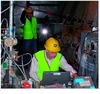
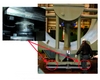
A system of lasers was used to measure the displacements of the large stationary components (shells, standards, exhaust hood) as the unit was operated. Multiple pedestal-mounted lasers were located around the turbine, and small prism targets were attached to the turbine at strategic locations.
The results of these laser tests confirmed that the predicted thermal and vacuum displacements matched the actual machine operation.
Thermodynamic performance was quantified using traditional power plant efficiency measurement techniques (following guidance from ASME PTC6.2). In addition, pressure and temperature rake probes were installed in the HP turbine exhaust and the IP turbine exhaust to capture the flow distribution at these locations.
The HEAT steam turbine HP section efficiency was confirmed to be the best in GE's experience with small volume flows, exceeding design expectations.
The steam flows within the end seal system were also quantified during these tests. Flows, pressures and temperatures were measured in the end packing leak-off, seal and vent lines to validate the end seal operation.
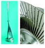
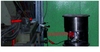
Details of the LP turbine aerodynamic performance were evaluated using traverse probes manually inserted radially into the LP turbine section while the turbine was at full load operation.
Test provisions were designed into the first unit specifically to allow this testing. The staging, exhaust hood, and diffuser extension were traversed at numerous axial and circumferential positions.
Applications
The A15 HEAT steam turbine was designed to be used in 109F combined cycle power plants in either single-shaft or multi-shaft configurations. Because the steam turbine is designed to be placed on the end of the single-shaft configuration and has its own thrust bearing, the same steam turbine can also be used in 9FA and 9FB multi-shaft configurations.
The A15 HEAT steam turbine product structure currently includes both unfired and up to 35% supplementary-fired HP turbine designs. The HP turbine operates on sliding pressure up to a throttle pressure of 165 bar (2400 psi), depending on the flow-passing requirements. HP turbine options can be expanded if additional supplementary firing is required.
The HP turbine design is paired with a combined IP–LP turbine section using available last-stage-bucket designs. As already noted, the first A15 HEAT steam turbines use the 1.07 m (42 in) and 1.21 m (48 in) axial LP turbines. LP turbine options can also be expanded if high exhaust pressure applications are required.
The A15 HEAT steam turbine also has extraction capability to support process steam or district heating. Extractions are available from the cold reheat flow (HP turbine exhaust), IP turbine admission, and LP turbine admission (IP turbine exhaust). Extraction options can be expanded (ie mid LP extractions for lower pressure steam) if required.
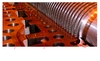
The Tynagh power plant, location of the first 50 Hz HEAT (A15) steam turbine A15 HP section on shipping supports A15 turbine installed at Tynagh The HP section is of the reaction type, with drum rotor construction Integral bucket and nozzle covers are used throughout the HP section Dual carrier design of the A15, allowing operating pressures in excess of 165 bar (2400 psi) Abradable coating (grey material) in the HP section, at the bucket and nozzle tips Further detail of dual carrier design The LP exhaust hood includes an innovative sliding system, allowing the IP/LP turbine to expand thermally towards the condenser The new 1.21 m last stage bucket During field validation testing a number of pedestal mounted lasers were used, with small prism targets attached to the turbine, to compare actual thermal and vacuum displacements with predicted. The picture shows a typical set-up, with the dashed red linTypical traverse probe test underway to evaluate the aerodynamics of the LP section. Traverse probes were manually inserted radially into the LP section while the turbine was at full load