INSTRUMENTATION AND CONTROL
Janschwalde upgrade helps keep coal power economic
23 June 2004Keeping coal and lignite fuelled power stations competitive during the dash for gas has been a major problem. Now that natural gas prices have started to rocket, advanced control system retrofits, including neural networks, are helping to recover economic operation in Germany's modern lignite and hard coal fired power stations.
Utility electric power generation plants generally need to radically revise control and instrumentation systems to maintain state of the art operations and maintenance regimes about every five years.
In today's operating environment power generators face the pressures of cut-throat commercial competition, increasing gas prices, unpredictable dispatch scheduling and the prospect of costly carbon emission control legislation, as well as a total lack of political planning to support new investment in power plants needed to replace the existing ageing fleet.
The need for extension of the economic plant life of the existing fleet of power stations as well as optimisation of performance parameters is becoming increasingly vital if the lights are not to start going out in the imminent future.
Already many new gas turbine combined cycle power plant projects are mothballed, back in the hands of the financial institutions who funded them, or being rebuilt at great expense to meet load following regimes they were never designed to handle.
Fortunately, the pace of advanced control systems development is increasing apace with the changes in the operating environment. The current operations by ABB to upgrade Vattenfall Europe's six 500 MWe lignite burning units at Jänschwalde and the 900 MWe units at Boxberg in the eastern Lände of Germany provide some interesting examples.
The 3000 MWe Jänschwalde combined heat and power station was commissioned over a period from 1981 to 1998 as the GDR's most modern power plant.
The power station, shown in Figure 1, is located adjacent to the Lausitz open cast lignite mines near the Polish border and the "chemical triangle" of Bitterfeld–Halle–Leipzig, close to the Sorbian town of Horno. Also located on the site is a key branch of the Cottbus Energy Resource Institute and the famous Cottbus demonstration PFBC combined cycle power plant is not far away.
Further advanced lignite burning power stations installed in eastern Germany since reunification include the 1866 MWe Lippendorf plant, 1600 MWe at Schwarze Pumpe, a new 907 MWe unit at Boxberg and a new 960 MWe plant at Schkopau. A hard coal fired 533 MWe power plant at Rostock built to provide intermediate load has been operating since October 1994, and the 1060 MW pumped storage hydropower plant at Goldisthal has recently started operation.
These have contributed to a 93 per cent overall reduction of SO2 emissions in the area, but increasing CO2 emissions are now becoming an equally urgent problem.
Key characteristics of the Jänschwalde plant are listed in Table 1.
The six units (A, B, C, D, E, F) incorporate identical basic heat circuits and are grouped together in three 1000 MW two-unit modules:
Module Y1 (Units A and B + Y0)
Module Y2 (Units B and C)
Module Y3 (Units C and D).*
In the years 1993-98, ie before the present upgrade, the unit-level main systems were upgraded and flue-gas desulphurisation systems retrofitted to alleviate the 400 000 t/a of SO2, ensuring compliance with statutory regulations, while improving performance and efficiency. During the same period, the process control system was also replaced, with Contronic E, and new module-level double-unit control rooms installed. The degree of automation was increased, but the operator control and monitoring activity required was about equivalent to the original system.
Upgrade programme
The basic task of the present upgrade project is to replace all or part of the existing I&C systems over the years 2003 to 2005, while minimising the outages incurred. The main features of the programme include upgrade of the human–machine interface system (with introduction of Maestro UX) and increased automation, while keeping the existing control system essentially intact. No functional changes have been made to tasks in the control rooms but staff numbers are being reduced.
With the successful implementation in 2003 of the first unit upgrade – Unit C of Module Y2 - which is being treated as a "master unit", the concepts now in place are considered to have been confirmed and further potential identified. Vattenfall issued the acceptance for this first unit in December 2003, and it is now serving as a template for duplication.
A further four units were scheduled to
be upgraded in 2004, with the sixth and
final unit to be completed in 2005. Completion of the upgrade for the Boxberg units is scheduled for 2006.
The upward compatibility of the existing Contronic E to the new Symphony/Maestro control system enables the automation programmes to be expeditiously implemented in Contronic E, with minor modifications. For the first unit minimal time was required for installing the modified programmes and starting up the new operator control system. It proved possible to do this even before the unit was actually shut down.
A total period of 65 days was available for implementation and commissioning. Punctually, on 6 October 2003, the first unit was back on line and, following extensive trials and validation runs, the operating procedures have now been optimised.
Parts of the operator control system for the general plant auxiliaries not previously upgraded had to be replaced and operator control actively integrated into the process control system. The systems are required to retain operational capability over a sustained period of 15 years.
The Jänschwalde power plant's remit is not only to operate as a baseload cogeneration plant, but also to provide network frequency control support.
To facilitate this, management of plant operation and operational work procedures has been optimised on the basis of comprehensive and updated process information.
Key tasks of the upgrade project include:
• Updating the human–system interface (communications) systems.
• Preserving and upgrading the control system at the field and automation levels while simultaneously increasing the degree of automation, with emphasis on reliability based, low-wear, optimal-life system operation.
• Modernisation of operator control, monitoring and management systems, with use of high-resolution VDU and large-screen projection technology.
• Increased plant availability (message optimisation, early detection of malfunctions).
• Carrying out the conversion work within the scheduled overhaul periods, without any additional plant downtime.
• Training the operating staff.
• Customising the service support.
Prior to the present upgrade, three control room operators had run a 500 MW unit (boiler 1, boiler 2, turboset/machinery). Unit/module-level FGD systems for each 2x500 MW module were operated by another control room operator. There was also a module manager in each double-unit control room. The plant-level FGD material supply and disposal systems were handled centrally by an operator in a separate FGD supply and disposal control room.
The electrical plant auxiliaries were operated from the general auxiliaries control room of each module.
Module Y1 was assigned some plant level systems, called Y0, while Module Y3 was assigned the flue gas desulphurisation material supply and disposal functions. The general auxiliary systems were in some cases operated using mosaic boards, eg for the flue gas desulphurisation section, but they were predominantly operated from dedicated control consoles by means of relay-based step selection functions.
The main purpose of the control room upgrade was to centralise control of each pair of units, with four people in the control room instead of eight (amounting to a reduction in the operating staff of 60 (= two persons per unit x 6 units x 5 shifts), radically cutting costs. The four control room staff now consist of one module manager plus three operators.
At the same time the policy was to retain the module-level "clearing offices". These offices are responsible for planning and administration of mechanical and electrical work-clearance/work-permit procedures during maintenance. This arrangement automatically assures conflict-freedom for current activities and for planned activities in any phase, including testing.
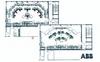
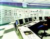
Figure 2 shows one of the old control rooms, while a new control room is shown in Figure 3.
Figure 4 compares control room layouts.
Modifications were necessary for a substantial portion of the existing control-system functionalities to assure fully automatic operation.
Ad hoc actions and manual interventions have been largely eliminated. Load changes and start-up procedures can now be carried out to optimum effect but the plant's existing sensors and actuators have been retained, including their automation functions and devices.
Figure 5 shows reduced start-up times resulting from the increased automation.
Upgrading unit 3 of the Boxberg power plant is a similar project. By 2005, the number of operator workplaces here will also be optimised.
Human–system interface
The new human–system interface (communications) systems, combined with the higher degree of automation, aim to significantly improve plant operations, with the following benefits:
• Increased plant availability.
• Early detection of malfunctions.
• Faster correction of malfunctions.
• Improved unit manoeuvrability.
• Shorter downtimes for overhauls.
• Reduced maintenance costs.
• Use of time-optimised start-up procedures
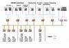
The new human–machine interface (communications) system (Figure 6) creates options for providing the operating and technical staff with the required information faster and more selectively. The principal measures include:
• Replacing the operator control, monitoring and management functions contained in the process control system for the 500 MW unit main systems, plus integration of the external systems.
• Upgrading the operator control, monitoring, diagnostic, maintenance, engineering, documentation and management functions of the process control system.
• Providing comprehensive information on the process control systems at PC workplaces in the power plant's administration area, for online process data evaluation.
Within the time schedule, some of the existing Contronic E programmes had to be modified, and all the graphical displays converted.
Neural networks
During the first half of 2004 ABB conducted studies on the improvement potential which might be achieved from use of combustion optimisation procedures based on application of neural networks to the Jänschwalde power plant (Figure 7). This holistic approach to optimising the combustion process promises increased efficiency and reduced emissions.
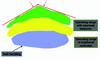
The neural net models the multivariable non-linear relationships of the combustion process (Figure 8). It learns the relationships between signals/parameters by analysing the historical data for them. So it is particularly appropriate for dealing with complex combustion processes, which cannot be readily described mathematically.
By experience and knowledge the operator is able to maintain a certain level of boiler performance. However, the performance can only be suboptimal since the influence of the individual parameters on each other cannot completely be validated by the operator.
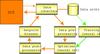
The Pegasus Power Perfecter system implemented by ABB claims to automatically recognise correlations, generate a model, and optimise operational parameters by applying this model. Also, it recognises changes in the real plant's behaviour and fits the model accordingly.
The neural net communicates with the control system via a serial link obeying the following rules:
• Release and protection criteria remain in the control system.
• The control system observes the proper function of the optimiser. In case of failure the DCS switches over to existing setpoints.
• Plant operation fully remains in the plant's operator station.
The system checks the collected process data. The optimiser starts with this initial plant state of operation and generates a set of optimised setpoints. Data post-processing checks for plant limitations, maximum rates of changes and calculates setpoint biases. The DCS monitors the heartbeat signal and, in case of failure, slowly turns down the biases to zero.
The variables most closely affecting efficiency are excess air and exhaust gas temperatures, whereas the NOx content is predominantly influenced by the combustion temperatures. The neural network uses the modelled combustion knowledge to find the optimum setpoint values for the different customer requirements involved.
In past projects up to 0.75 per cent heat rate improvement was reached while maintaining emission limits, thereby achieving a return on investment of between 1-2 years. The main control variable inputs to the boiler model concern: air valves at each burner; burn-up air valves; total air quantity; primary air flow rate; secondary air flow rate; support air temperature; recirculation gas quantity; distribution of coal mill loads. The model can be used to examine the effect of such influences as: coal quality; mill wear; boiler degradation (higher furnace temperature for same energy transfer to steam) etc.
TablesTable 1. Main characteristics of the Jnschwalde power station