Transmission & distribution
LIPA's superconducting future
1 March 2007Installation work on a high temperature superconductor HV link on Long Island, New York, will begin soon. When the link enters operation in September, it will be the longest and most powerful HTS cable in a live grid at transmission voltage.
Installation of the 600 m cable will take place in three stages – one for each of the cable phases – with the first starting in April. The US Department of Energy, which is providing approximately $15m, half the project’s funding, chose American Superconductor Co (AMSC) as the prime contractor. AMSC is also the provider of the high temperature superconductor (HTS) wire for the cable. Partners in the project, which is a DOE ‘Superconductivity Partnership Initiative’, include Nexans, the manufacturer of the cable and the cryostat (which houses the liquid nitrogen coolant) and Air Liquide, provider of the refrigeration equipment. The host utility, Long Island Power Authority (LIPA), is providing transmission planning, and following installation, will operate the HTS cable system. When the cable is energised it will be the first HTS cable to operate in a live grid at transmission voltage. Operation will begin in September, after the summer months with their typically high power demands.
The plan is that the HTS cable will operate in the LIPA grid for a minimum period of one year. Following this formal trial period, which will culminate in an operational performance and economic review, LIPA will have the option of retaining the new superconductor cable as a permanent part of its grid. The cable system is to be connected at both ends to the existing power grid. It will operate at 138 kV and carry 2 400 A resulting in a capacity of approximately 574 MW. In addition, the cable has been designed to survive a fault current of 69 000 A. The project has not been hindered by siting restrictions, as the cable will be laid in an existing right-of-way between two substations at Holbrook, New York.
Potential of HTS cabling
LIPA’s choice of an HTS cable is motivated by its long term plan to upgrade its grid infrastructure to cope with inevitable increased power demands. HTS cables have much higher power density and lower resistive losses than conventional cables but remain expensive. However, LIPA believes that HTS cabling will eventually prove itself to be less costly than conventional 138 kV-to-345 kV upgrades, especially with the emergence of new generations of superconductors. LIPA sees the present financial backing from the DOE as necessary support until that point is reached.
LIPA and AMSC are also considering longer term plans to install high capacity, low environmental impact HTS cables elsewhere in the grid to tackle the area’s growing power needs. The authority hopes that it can increase capacity, by a factor of between two and five, within current right-of-way constraints to meet its forecast increasing power demands.
Cable structure
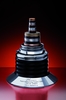
The Nexans manufactured cable being used in the LIPA installation is of the ‘coaxial, cold dielectric’ type. Cold dielectric systems differ from the earlier warm dielectric designs in that their outer insulation layer is maintained at cryogenic, rather than at ambient, temperature. Warm dielectrics have a number of drawbacks including limited power capacity and the presence of stray electromagnetic fields.
The LIPA cable consists of a central core that serves as a flow path for the liquid nitrogen coolant. Superconducting tapes, designed and supplied by AMSC, are wrapped around the core and make up the phase conductor, replacing copper or aluminum in conventional cables. The 0.4 mm thick multifilament HTS tapes are of the first generation type. The Bi2Sr2CaCu2O8 (BSCCO) HTS filaments are embedded within a silver matrix, which is laminated with brass. The tapes , 128 km of which will be used in the LIPA project, are then covered with a dielectric that provides insulation at temperatures of around minus 200°C. A second layer of HTS tape is wound on top of the dielectric to form the outer shield conductor. Lastly, the finished cable is housed in a thermal envelope. This consists of a double walled vacuumed stainless steel pipe. Nexans has designed the pipe’s vacuum to have a lifetime of ten years. Between the two walls of the pipe is a superinsulating aluminium coated foil.
The outer layer of HTS captures all, or almost all, electromagnetic fields emitted from the phase conductor, resulting in a fully, or almost fully, shielded cable design. This occurs because in very low impedance (VLI) cables the shield conductor current flow is equal, but opposite in direction, to the phase conductor current flow. The elimination of stray EMF has the benefit of avoiding current losses from nearby metallic structures and interference with other surrounding electrical cables. This permits more compact installation, requiring much narrower rights-of-way.
Development
The installation at Long Island will mark the end of a two and a half year design and development process consisting of an original design period, begun in 2005, and a year’s testing of the 30 m cable prototype at Nexans’ Hannover site, which ended in late 2006.
The design and development stage began with the production and testing of two terminations along with the 30 m trial cable. In addition several prototype manufacturing processes were tested to verify that the cable manufacturing process would not harm the superconductor tapes and that the cable could withstand bending. Samples from these manufacturing prototypes were also tested for dielectric performance to observe the performance of the dielectric design under industrial manufacturing conditions. The testing phase also incorporated testing and modelling to determine the effect of fault currents on the cable.
The cryostat system was also tested to verify operating parameters such as heat loads.
The refrigeration system was in fact that used in an earlier project, the Pirelli Detroit Edison demonstration. In late 2001, this project succeeded in installing the first retrofit underground HTS cable, which was of a warm dielectric design (120 m, 100 MW, 2 400 A, 24 kV) at Detroit Edison’s Frisbie substation. The project was halted a few months after installation by a failure attributed to defective welding on the cryostat, resulting in loss of vacuum. The Detroit Edison refrigeration system was shipped to Long Island, and adapted for the needs of the LIPA project. Adjustments included an upgrade of the cooling capacity by 38%, installation of a new 9000 gallon liquid nitrogen tank, provision of a remote monitoring and control function, and installation of a new buffer for fault reaction and recovery.
Other projects
In addition to the Detroit Edison 24 kV cable demonstration three other earlier warm dielectric projects are noteworthy. In February 2000 a 30 m, 27 MW, 12.4 kV, 1 250 A, HTS cable developed by Southwire and Oak Ridge National Laboratory began operation in a Carrollton substation to supply power for three Southwire plants. The cable remains in successful operation, but discussions continue concerning its future. In May 2001, a 30 m, 30 kV, 2000 A cable was installed by NKT Cables, in Copenhagen Energy’s grid at Amager. In 2003 the system was disassembled after having delivered 226 GWh of energy. The results of cost and technical analyses proved mixed. Although no problems were encountered with the HTS cable itself, and the system’s cost profile remained favourable, it was concluded that the cooling system did not offer the reliability needed for continuous operation (malfunction of the cooling system in the start-up phase and excessive vibrations during operation were observed).
In 2004, a 30 m, 35 kV, 2 000 A, warm dielectric cable was put into operation by Innopower Superconductor Cable Co Ltd as part of the 35 kV bus line for the Puji substation at Kunming, Yunnan. The Chinese project is still running successfully. Nexans provided the cryostat, HV dielectric, and cryogenic couplings. Innopower, in collaboration with the State Grid Co and the Department of Science and Technology, has been looking at plans to develop a 300-400 m HTS transmission line in China.
On the back of their respective experiences with warm dielectric cables, NKT and Southwire, in a joint venture under the name of Ultera, were awarded a $9m project by the DOE to demonstrate a new, cold dielectric cable design at American Electric Power’s Bixby substation, Columbus, Ohio. This uses second generation HTS cables, which employ YBa2Cu3O7 (YBCO) tapes. The triaxial cable consists of the three phases arranged in concentric HTS layers.
The development stage at Bixby included design of a simplified cryogenic system by Praxair that avoided the problems faced by NKT in Copenhagen. Following successful testing, beginning in 2003, of a 30 m, 12.4 kV, 1 250 A link also in Carrollton, the full scale 200 m, 69 MW, 13.8 kV, 3 000 A system was energised. It has now been in operation in the municipal grid for seven months.
In July 2006, an underground HTS cable began a six month transmission demonstration between two National Grid substations at Albany, New York. The $27m project, which, like the LIPA project, is receiving 50% of its funding from the DOE, has SuperPower Inc as its main contractor, with the cryogenic system and cable infrastructure provided by BOC and Sumitomo, respectively. The demonstration operated without incidents or interruptions for over 2 700 hours of continuous operation until November 2006, before the occurrence of the first fault – caused by an external flashover in a nearby substation – which did not affect the cable.
The project’s 350 m, 48 MW, 34.5 kV, 800 A cable, just over half the length of that to be used by LIPA, is also of a cold dielectric design, yet differs from the Ultera design – where the phases are concentrically arranged – in that the three phases are housed within one cryostat. This allows a more compact cable system – 150 mm diameter compared to the 600 mm required for a conventional cable arrangement – as well as reduced heat invasion. The HTS tape is a first generation, bismuth based design, like that used in the LIPA project. It is planned that sometime in 2007 a 30 m section of the cable will be replaced with YBCO tape.
Next generation HTS
Nexans is also working on the development of second generation HTS cables. During the summer of 2004, the e5m ‘Super3C’ (Super Coated Conductor Cable) project was set up by the European Commission as part of its ‘Sixth framework programme for research and technological development’. The Nexans co-ordinated project’s general aim is to investigate the feasibility of low loss YBCO HTS cables. Whilst its specific aim is the eventual development, manufacture and testing of a 30 m long functional single phase 48 MW, 10 kV, 1000 A, second generation HTS with terminations.
Why HTS?
Cost remains an impediment but proponents of HTS cabling stress the possibilities that wider use of the technology could open up. For instance, the ability of HTS cabling to carry more current at lower voltage over longer distances than conventional cables of equal dimensions, could allow new generators to be located at greater distance from urban loads (where land, labour and other costs are lower), while providing the same degree of voltage support as if they were located in or adjacent to the city centre. Thus, HTS transmission lines could be deployed as ‘virtual generators’ to solve both power supply and reactive power problems.
VLI cables could be used to more easily ‘pull’ power onto high capacity pathways that flow directly into a congested load pocket than to site, construct and ‘push’ comparable quantities of power to the same spot on the grid using conventional approaches. In addition, impedance may be added to a VLI circuit, simply and inexpensively, by installing conventional substation equipment, eg inductors or PARs, yielding effective control of flows along current ‘hogging’ VLI cables. Therefore, VLI superconductor cables can be configured to function like fully controllable DC circuits, whilst operating in the synchronous AC environment, thereby potentially avoiding the cost of AC/DC converter stations.
Construction of further overhead cabling in congested urban areas is often infeasible owing to siting restrictions. However, the unobtrusive nature of HTS cabling is suggested as a potential means of overcoming such restrictions. The insertion of short link VLI cable into congested interfaces can ‘attract’ power flow away from other grid elements operating at or near their limits. Such a strategy could increase grid capacity more cost effectively and, at the same time, improve the life of the existing grid elements, eg through the prevention of overheating and dielectric ageing.
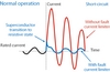
Test area for LIPA project cable, Hannover, Germany Location of LIPA superconducting project on Long Island LIPA’s coaxial, cold dielectric cable Operating principle of FCLs