Emissions reduction
More understanding, less hardware: cleaning up at Claus
1 May 2007Innovative engineering has solved emissions and performance issues at unit A of Essent’s Clauscentrale plant – with minimal outlay on new hardware.
Clauscentrale (Figure 1) is a 1280 MWe power plant situated in The Netherlands. Consisting of two 640MWe Stork supercritical boilers firing bio-oil, heavy fuel oil and natural gas through 18 opposed fired burners (Figure 2). Unit A entered operation in 1977. “So we knew that with the new LCPD regulations and new trading schemes coming in, we had to undertake some fairly major modifications to the plant,” says Jos Peeters, Essent senior asset engineer. “We were also aware that we had some other issues related to furnace vibrations, flame instability, and boiler performance which we wanted to resolve at the same time. And we wanted to achieve all this while keeping downtime to a minimum and keeping the financial outlay on new equipment and hardware as low as possible.”
Burning gas, the original NOx level was ~400mg/m03. The targetted NOx level for the modified plant was <200mg/m03, while oil-fired emissions had to be kept below 400mg/m03.
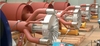
To achieve these reductions burner modifications (Figure 3) and increased flue gas recirculation (FGR) were applied at Clauscentrale A. The unit has been firing with these modifications since November 2005.
The project was carried out by RJM. “In early 2004 we investigated the work the company had done at several locations in the USA and were impressed by their approach of really understanding what is going on at every stage of the combustion process and working out what factors affect key performance criteria,” Jos Peeters notes.
As already mentioned, one of the major problems was the flame instability of the original units, resulting in excessive primary reheater metal temperatures and severe furnace vibrations at higher excess oxygen and FGR rates. The solving of this problem was a key objective of the upgrade. Also, as these boilers can be operated remotely by Essent’s electricity traders any improvement in the operation of the unit across its load range would be beneficial. When changing boiler load with the original burners, burners had to be turned on and off at certain load points. If all burners could remain in service across the turndown range of the unit this would enable the operators and traders to react much faster to the needs of the market.
These issues made the emissions solution more complex and therefore the engineered solution required careful and thorough study.
Using computational fluid dynamics (CFD), a single burner model was employed to investigate three factors: stability; NOx reductions due to mechanical changes; and NOx reductions due to increased FGR flow rates. A full furnace model was used to investigate a fourth factor, namely changes to furnace exit gas temperatures (FEGT) at higher FGR flow rates.
It was also recognised that these units had never before run at FGR rates above 10% so to confirm that no detrimental effect on boiler performance would occur, a boiler performance study (BPS) was carried out to check whether the change in mass flow through the convective heat exchangers would adversely affect steam output conditions, vibration (vortex shedding), desuperheater spray flows, FD fan capacity and heat exchanger metal temperatures, particularly the already marginal metal temperature limits of the primary reheater.
To consolidate the two models the CFD engineer and the BPS engineer checked that the inputs to both models were the same and that furnace gas exit temperatures of each model were in agreement with each other.
CFD modelling
A model of a single burner was constructed so that the geometry of the flame stabilisers, new gas pokers and spray patterns could be examined and compared in detail to the existing burner. Single burner models allow detailed investigation of burner design and quick optimisation of components.
In addition to the existing configuration (Figure 4), a model of the proposed modification was developed, featuring exact poker drillings to ensure accurate flow representation.
As well as developing the single burner models, a full furnace model of the upgrade configuration was constructed. For computational speed, and since the furnace is fully symmetrical front to back, only half of the furnace was actually modelled, and a symmetry plane was imposed.
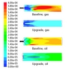
Using the simplified geometry established from the modelling effort, a combustion model was then used to calculate temperature and flow fields for both the existing and proposed upgrade geometries. The temperature fields were used to simulate and confirm the improved flame stability of the upgrade design at higher FGR rates. The output is shown in Figure 5.
The 0% FGR figure compares the temperature contours (°C) for the existing geometry and proposed upgrade. In both cases, high temperature zones are shown near the burner outlet. This is as expected, as a stable burner will include features in its geometry that maintain flame stability. This stabilised flame is by definition near the burner. It is through examination of the temperature contours that instability can be identified.
For the 6% FGR case, there is no difference from what was seen at 0% FGR except for modest reductions in temperature.
For 15% FGR, significant variations are observed. The existing geometry shows no high temperature region near the burner. Instead, the entire high temperature region is located 3-4 burner diameters downstream (3m - 4m distance). In this configuration, reliable combustion seems to be occurring, but because there is no point where the flame always exists, it is the type of flame that will experience large scale movements. These are observed in the field as furnace “rumble” or combustion driven vibration.
In contrast to the existing geometry, the proposed modification maintains a high temperature region near the burner which will ensure the combustion driven vibration will not occur.
For 23% FGR the existing configuration still reliably combusts the fuel and oxygen, but the flame is detached from the burner (large scale vibration would be anticipated) while the proposed modification still has a high temperature region near the burner. Full furnace simulations were run for gas and oil fuels at 0% and 15% FGR rates. This was done to compare furnace exit gas temperatures with the boiler performance modelling also carried out.
In addition, absolute NOx estimations from the models were compared with single burner predictions, as an independent check (Figure 6).
The CFD modelling led to the following conclusions:
• Burner modifications, which included new staged flame stabilisers, low NOx gas lances and low NOx atomisers, were shown to produce stable flames.
• Burner stability was demonstrated on gas, from 0% FGR to 23% FGR.
• Baseline CFD compared well with the baseline field test data.
• Calculated furnace exit gas temperatures compared well with the boiler performance evaluation done to ensure boiler performance at higher FGR rates.
• The emissions objectives of the project would be met, with NOx for natural gas <200 mg/m03 and for palm oil <400 mg/mg/m03, and both would be achieved while operating with CO emissions of <175 mg/m03 (@3%O2 dry).
Boiler performance study
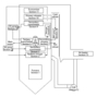
The baseline performance data were used as inputs to the boiler performance study, together with the construction detail of the boiler (heat exchanger design, number of tubes, diameter, wall thickness, material, etc). The nodalisation diagram (Figure 7) shows the flow arrangement and the heat exchanger arrangement of the boiler.
The baseline model was run and adjusted until the outputs matched the actual baseline unit operating data. Following this the model was then re-run with different FGR rates for gas and oil firing conditions to check for any adverse effect on the boiler performance. The table above shows an excerpt from the natural gas comparison.
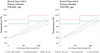
For the critical primary reheater metal temperatures the graphs in Figure 8 highlight the anticipated effect of higher FGR flows and confirm no negative effect on metal life up to FGR rates as high as 20%. The results of the boiler performance study showed that no detrimental effect on boiler performance and metal temperatures would be expected.
The study also confirmed that there would be no increased vibration potential with the higher quantity of FGR flow with either natural gas or oil and no adverse effect on FD fan duty.
Figure 1. The Clauscentrale plant Figure 2. Original NOx burner and New low NOx burners installed and firing Figure 3. The RJM burner upgrade involved replacement of the centre section of the low NOx burner Figure 4. Existing burner model geometry Figure 5. CFD output: temperature fields Figure 6. CFD output: NOx fields Before: the original low NOx burner flame. The flame is detached from the burner throat After: burner flame after modifications. The flame is both attached and stable Figure 7. Nodalisation diagram for Clauscentrale Figure 8. Effect of higher FGR flow on primary reheater metal temperatures