coal power
Wet vs dry bottom ash handling compared: one plant's experience
1 June 2007A multi-unit coal-fired power station where both dry and wet bottom ash handling systems are employed provides an opportunity for detailed comparison of the two approaches.
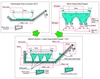
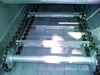
Dry systems have significant advantages for bottom ash handling at coal fired power plants, with considerable environmental and economic benefits in the case of both new build projects and replacements of existing wet systems. At present Magaldi is uniquely placed in the dry ash handling field to demonstrate, analyse and quantify the benefits of dry over wet ash handling. The company has installed, since 1985, some 90 dry ash handling systems (of the MAC (Magaldi Ash Cooler) type - see Figures 1 and 2) around the world, in both new boilers and as retrofits.
The Magaldi R&D department has been monitoring the feedback from customers with the aim of evaluating the operating performance of dry systems since start-up.
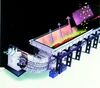
In understanding the benefits of dry bottom ash extraction systems compared with wet systems, a particularly meaningful comparison can be done in the case of plants where both systems are installed. Very often it is at the older plants, which frequently adopt a policy of progressive replacement of existing wet systems with dry systems at the units on a given site, where both types of technology can be found running side by side for several years. The study presented here was carried out at just such a plant, which has four 314 MWe coal fired units (Figure 3).
Dry vs wet – a case study
The standard wet systems can generally be divided into two categories: water impounded hopper systems; and submerged chain conveyor (SCC) systems. All the plants where these systems are installed complain about huge water consumption, high maintenance costs due to corrosion and clogging, environmental issues due to leakages of contaminated water and loss of boiler efficiency, and negative effects on boiler operation due to the low reliability and poor maintainability of wet systems.
The plant featured in the study described here was designed for baseload operation and the wet system, coexisting with the dry, MAC, system, has particularly high dependability relative to standard wet systems. To achieve this the wet system design in this case is in fact a hybrid of water impounded hopper system (which traditionally uses a sluice system) and an SCC system, serving both bottom ash and pyrites handling. In this installation the high reliability of the wet system has been achieved by incurring a higher capital cost than that for a standard wet system, necessary to provide the redundancy required for much of the equipment.
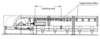
The core of the wet system is shown schematically in Figure 4. The water impounded hopper, which receives the ash from the bottom of the boiler, is equipped with slide gates that are periodically opened for dumping water and ash in the SCC system. Furthermore the slide gates allow maintenance to be performed on the SCC system without taking it out of service.
The introduction of dry ash technology started at the plant in 2004. At the time of writing two of the wet systems had already been replaced by MAC systems while a third unit is currently being retrofitted with boiler start-up scheduled for this June. By 2008 all four units will be dry, equipped with MAC systems.
The bottom ash feed rate per unit ranges from 1 to 2 tons per hour, with an unburned carbon (UBC) content of around 6.5%. The fly ash feed rate per unit ranges from 11 to 16 tons per hour, with a UBC content of less than 7%, which is the highest value that can be tolerated for reuse in the local cement industry. The rejects from the five coal mills (almost all pyrites) range between 0.05 to 0.15 tons per hour for each mill.
It is only by using a water impounded hopper in conjunction with sliding dump gates and an SCC system that the wet system achieves the high availability required. This would not have been possible with a traditional wet system.
As already mentioned, however, the wet system configuration adopted leads to much higher capital and maintenance costs as well as great space demands to accommodate the equipment layout.
The company which owns and operates the plant supplied us some data about the operation of both systems, allowing us to evaluate the performance of each, as summarised in Table 1.
It is not possible to generalise the quantitative analysis of benefits resulting from the implementation of a dry system, as these depend on plant specific conditions. Some benefits can be more significant than others, depending on plant characteristics. However, from Table 1 it is easy to gain an appreciation of the major benefits deriving from the MAC system in this particular plant.
Adoption of the dry system results in a water saving of about 258000 m3 per year, a significant quantity, not least in terms of costs. In the plant under consideration, each unit employing wet handling has a dedicated system for water circulation and treatment. Then the waste water from these units is sluiced into a centralised sludge treatment system. So the elimination of the wet systems also eliminates the need for the associated water circulation and treatment systems, reduces demands on the centralised sludge treatment system, lowers maintenance costs arising from corrosion and jamming along the sluicing lines, creates a cleaner and safer working environment due to the reduction in the number of places that need to be cleaned up (Figure 5), lessens power demand due to the elimination of water circulation pumps, and reduces the environmental impact of the power station thanks to the water savings and lower releases of contaminants. Table 2 shows results of a chemical analysis by the power station laboratory of the sludge typically produced by the wet systems, in which we can see the presence of undesirable elements.
Generally, the implementation of a dry system also greatly reduces ash disposal costs. These costs depend on specific plant characteristics and usually include, in the case of wet systems, storage costs in dedicated silos, transport costs and the costs of disposal outside the power station boundary.
In the power plant case considered here, however, these costs are not that high because the final disposal is inside the power station boundary and the utility owns large areas of unexploited land in the vicinity of the plant.
Nevertheless, the implementation of a dry system along with pulverisation of the dry bottom ash allows disposal costs to be transformed into revenues, via the selling of fly ash mixed with pulverised bottom ash to the local cement industry.
Another benefit from the adoption of a MAC dry bottom ash system is an increase in boiler efficiency due to the recovery of much of the heat leaving the boiler through the lower opening. This heat is the sum of radiant flux from the furnace, sensible heat and the chemical energy contained in the bottom ash due to its unburned carbon content.
For the power station studied here, measurements show that the losses at the bottom of the boiler are 1516 kWt for a single wet system against 200 kWt for a single MAC system, meaning a net thermal power saving of 1316 kWt per MAC system.
When we take into account the lower coal consumption (resulting in reduced power use by boiler auxiliaries such as coal mills, as well as induced and forced draft fans etc) and the lower power demand of the MAC system itself relative to the wet system, we can attribute a further 301 kWt of savings to each MAC system. The total boiler efficiency improvement of 0.196 percentage points results in 3700 t less coal consumption per year, corresponding to 9000 t of avoided CO2 emissions, with the associated additional environmental and economic benefits.
This comparative analysis of a dry, MAC, system and a wet system co-existing in the same power station has therefore shown that significant benefits derive from the dry system, even relative to the high performance wet system installed at this particular plant. The study lends justification to further investment in the replacement of wet systems with MAC systems at the other two units of the power station.
Superbelt vs chain conveyor
Apart from the overall benefits of dry over wet, experience in the plant that we have examined also confirms once more that the Superbelt solution (basically a steel mesh belt conveyor coupled with overlapping steel plates, see Figure 6) applied to dry ash conveying (as in the MAC system) is much more dependable than a chain conveying system, for both wet and dry systems.
The maintenance records for the wet ash chain conveyors installed in the plant under examination show that the whole chain is replaced every four years with other interventions required on the chain once a year for replacement of short sections.
At this particular plant, thanks to the presence of slide gates at the bottom of the water impounded hopper, maintenance work on the chain can be performed without interfering with boiler operations. However with traditional SCC systems such interventions require the boiler to be shut down, leading to high costs in terms of lost power production.
On the other hand the Superbelt installed at this station has been kept in operation without any recorded maintenance interventions needed on the belt itself and only minor interventions on the MAC system as a whole (eg, idler replacement, greasing of bearings, etc) without requiring boiler shut down or load reduction.
In fact our experience overall with the Superbelt suggests we can expect on average ten years of continuous running without interference with boiler operations for maintenance on the belt.
We believe the Superbelt design itself gives the system an intrinsic high reliability compared with a chain system.
One or more instances of damage to the steel mesh, for example, do not lead to belt failure, allowing the system to be kept in operation.
On the other hand with a chain type conveyor the reliability of the system depends crucially on the reliability of the rings in a single chain. Even if the rings are highly reliable by themselves (let’s say at time t the single ring reliability, R(t), is 0.9999), as the chain length grows, the whole-chain reliability decreases (eg, for a chain length of 60 m, the number of chain rings, n, is 600 and the whole-chain reliability, Rtot(t), is R(t) to the power of n, which is 0.9999 to the power of 600 = 0.942).*
Drive for the Superbelt is provided by a traction drum. This concept, widely applied for belt conveyors, is generally preferred to a round link chain system because, in the case of any blockage along the conveying line, the slippage between the belt and the drum limits the resulting traction forces and lowers the possibility of further damage. Also, with a plain drum we don’t have a situation where damage to just one sprocket tooth can cause system unavailability.
The Magaldi Superbelt is designed to avoid sliding friction, which can cause accelerated wear phenomena. Only rolling friction is allowed between the moving parts. This reduces maintenance and spare parts requirements and lowers costs.
In the dry conveying sector, different solutions have been developed to withstand the overload conditions caused by impacts from large ash lumps. We have chosen to oversize the conveyor belt support in the loading area by increasing the number of supporting rollers (Figure 7), giving the system considerable sturdiness. This approach also improves maintainability because, in the case of failure of one or more of the supporting rollers, the system can be kept in normal operation while maintenance activities are performed.
Another factor contributing to the reliability of the dry system is the use of a small auxiliary chain conveyor below the Superbelt for fine ash removal. This “spill chain conveyor” system, Figure 8, is a design feature adopted by Magaldi to increase dependability. It essentially sweeps up fines from the bottom of the main dry ash conveyor and is a very simple and reliable device for fine ash removal.
Even though the spill chain conveyor requires an additional 40-50 cm of height for its installation, it increases the overall dependability of the system and reduces the need for unplanned maintenance activities.
In contrast, in the plant under examination, the wet system has experienced problems due to the build up of fine ash deposits at the back end of the SCC. The SCC system scrapers, in the back run towards the tail drum, drag on the floor. Even though the SCC system is designed to have a clean and dry return side, the inevitable imperfections arising during installation and the dimensional drift caused by wear and deformations during operation result in the uncontrolled build up of wet ash piles at the back end, as can be seen in Figure 9.
Cumulative experience
The MAC system is now employed on 29000 MWe of installed capacity and has amassed 4.3 million cumulative hours of continuous operation without the need for significant maintenance.
Cumulatively this amounts to 15 million tons of ash extracted, cooled and processed for reuse and about 80 million m3 of water saved. And with recently ordered systems coming on line shortly (including installations at Kansai Electric’s 900 MWe Maizuru 2 unit in Japan, at Comision Federal de Electricidad’s 651 MWe El Pacifico plant in Mexico, Endesa’s 577 MWe Almeria 1 in Spain and Griffin Group’s 208 MWe Bluewaters 1 in Australia), the experience base will grow significantly in the near future.
Figure 1. Dry bottom ash extractor and cooler (MAC system) Figure 2. Inside the MAC dry bottom ash system. This is the ash receiving section Figure 3. The four-unit plant where the detailed comparison between wet and dry bottom ash handling has been carried out. Both systems are in use at this site, providing a meaningful basis for comparison Figure 4. Outline of the wet system considered in the comparative analysis. It is a hybrid solution consisting of water impounded hopper combined with submerged chain conveyor (SCC) Figure 5. Upper picture: clean-up operations on a wet system (SCC). Lower picture: dry system – a cleaner working environment Figure 6. Superbelt: steel mesh belt with overlapping steel plates Figure 7. To cope with oversize ash lumps extra supporting rollers are used in the loading area of the Superbelt conveyor Figure 8. "Spill chain conveyor” system Figure 9. Unexpected overloading of a plate in the fine removal run back end of the SCC